Before I ordered the timber for the internals of the boat, I drew the following sketch showing the lumber that would be needed.
 |
| Sketch of interior lumber |
There are quite a number of pieces of wood (in green) going across the width of the boat which I have called 'deck beams'. These pieces of wood cannot be straight. They need to have curves that are consistent with the curves defined on the plans for the the Transom, Frame 1 and Frame 2.
 |
| Frames & Transom |
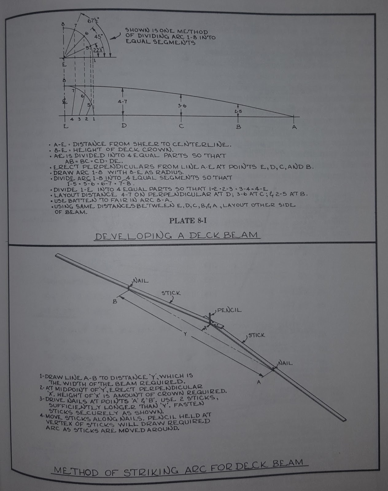
The quandary is how to know what curves to cut. The simplest solution would be to simply copy Frame 2 for the forward deck beams and then 'eyeball' the aft beams based on Frame 1 and the Transom. I suspect this 'eyeballing' method would have been fine especially given it all needs faring anyway and that epoxy can fill gaps admirably. I wasn't satisfied with that approach and wanted a more analytical way of developing the deck beams. Glen L Witt's book, 'Boat Building With Plywood' gives some methods of developing deck beams.
 |
| Plate 8-J from 'Boatbuilding With Plywood' |
Initially, I considered making the jig shown in the bottom half of the image above but I decided it would be easier to do the maths to work out the formula for the curve the jig would scribe. The development of the formula is shown below.

I think maths is beautiful because it can describe with infinite perfectness the truths of geometry.
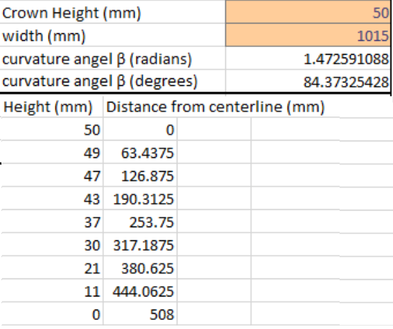
With these formulas I can now plot a deck beam for any width and any given crown.
The concept is that you have a consistent β angle across your whole deck. The crown of the deck changes as the width of the boat changes but the β angle remains the same. The curvature of the deck is defined by the β angle.
Using the plans, I measured the width and crown of the deck beam on Frame 2 which allowed me to calculate the β angle which will define the curve of the deck. With the β angle I could then generate a curve for any point on the deck of the boat by simply measuring the width at that point. (Obviously, at the very front of the boat the width is 0 so the height of the deck beam is zero at that point. The formula makes that clear as the term (W+2d) will equate to 0 when the width W = 0 and d therefore by necessity equals 0.)
With these formulas I can now plot a deck beam for any width and any given crown.
The concept is that you have a consistent β angle across your whole deck. The crown of the deck changes as the width of the boat changes but the β angle remains the same. The curvature of the deck is defined by the β angle.
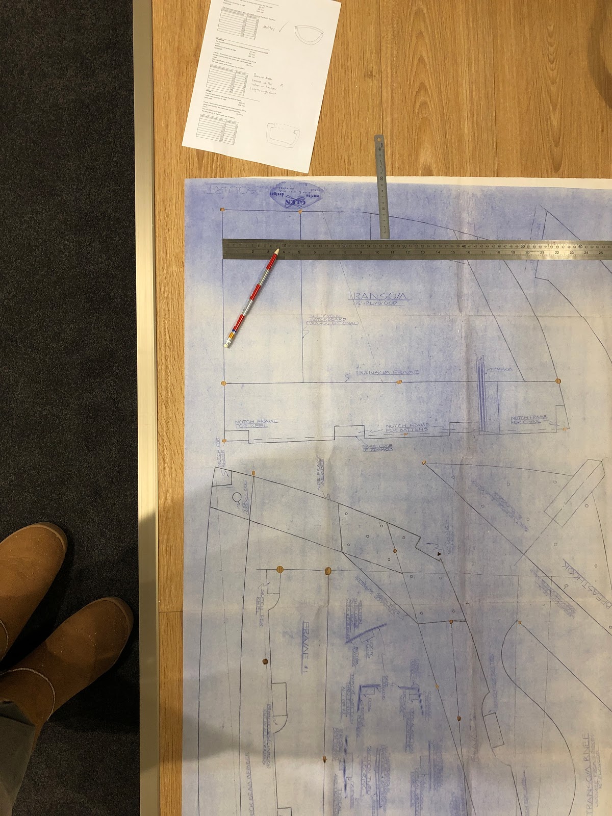 |
| Measuring the crown and width of transom on the plans. |
Frame 2 was calculated to have the following crown and width.

 |
| The Beams |
For the beam between the Transom and Frame 1
For the beam at Frame 1 (this beam will be the seat backrest)

Ironically after I finished cutting out the beams I read the instructions which say:
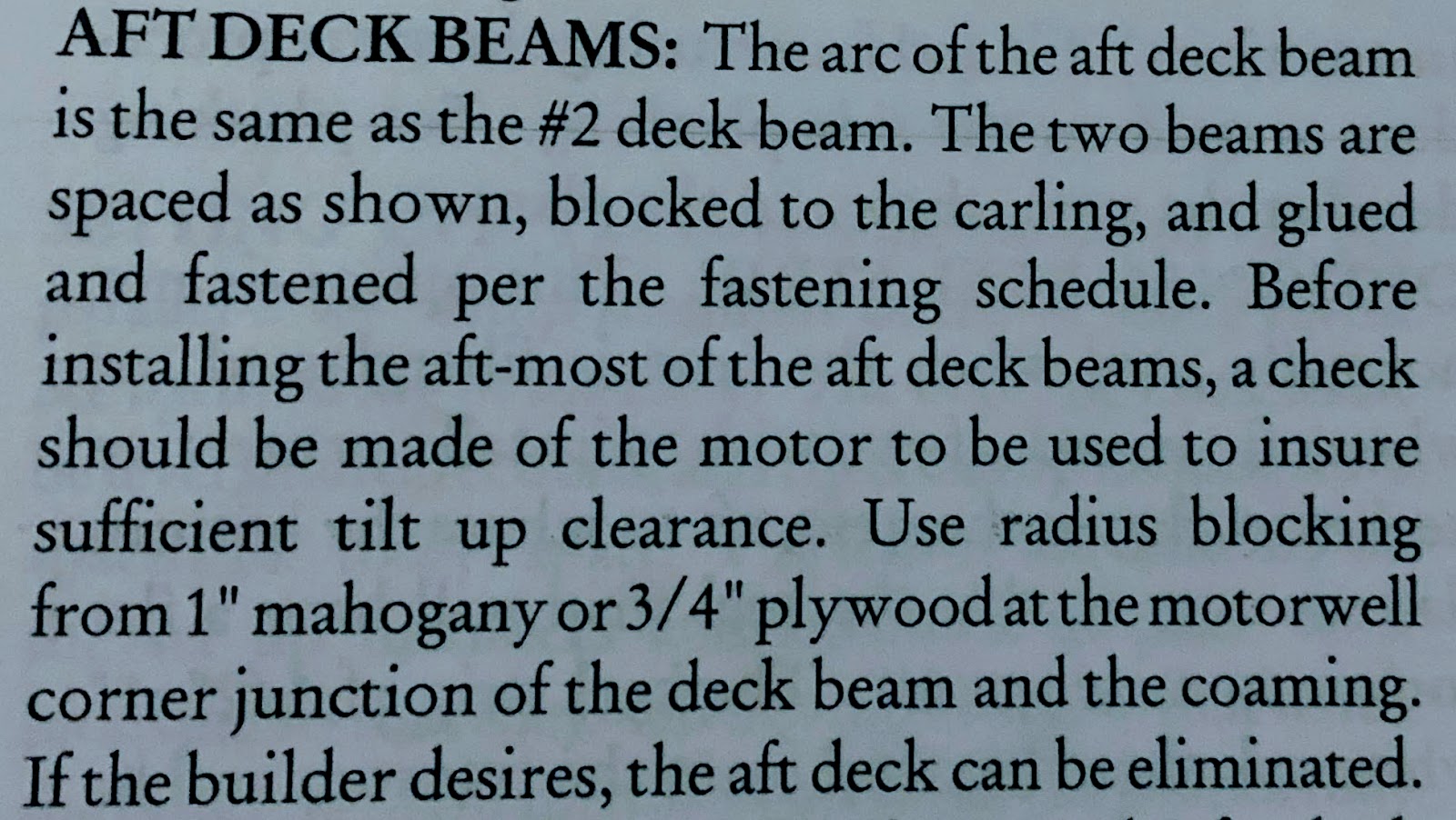 |
| Pro Tip - READ THE INSTRUCTIONS! |
Next post will be all about the internal framing!
No comments:
Post a Comment