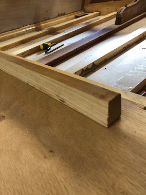
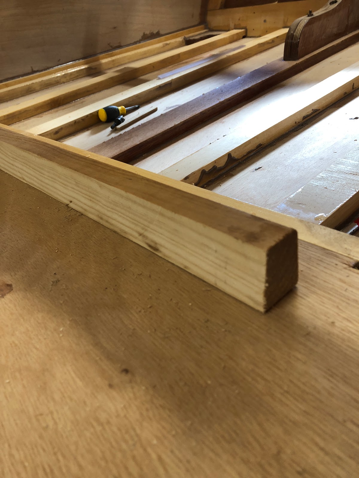
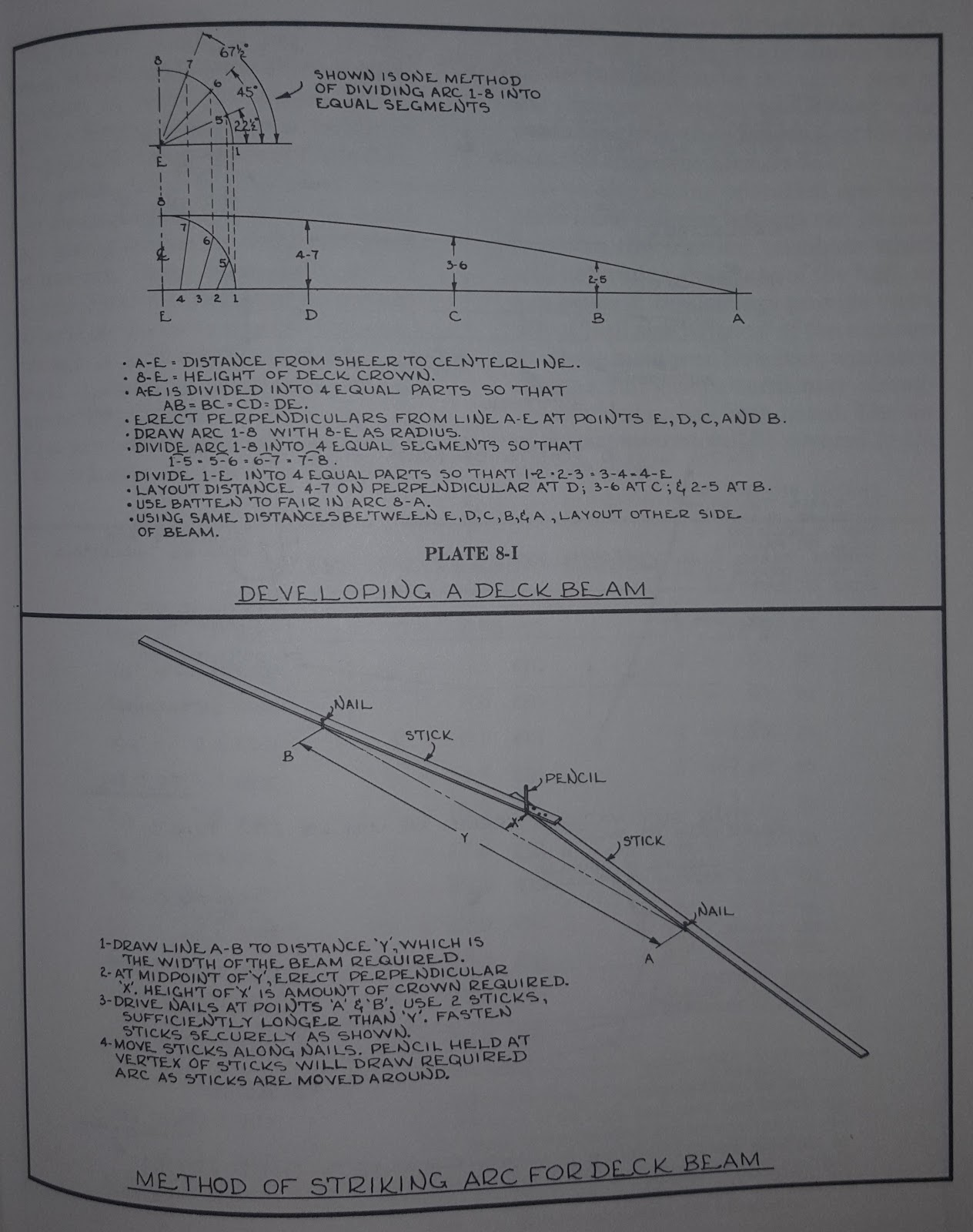
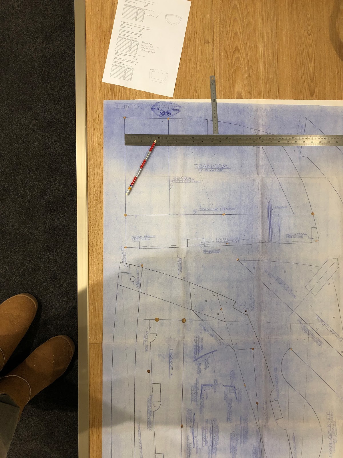
After installing the coaming and determining the deck beam curves, I marked out and cut the deck beams.
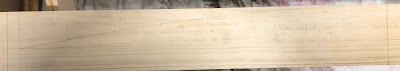 |
| Marking out one of the deck beams |
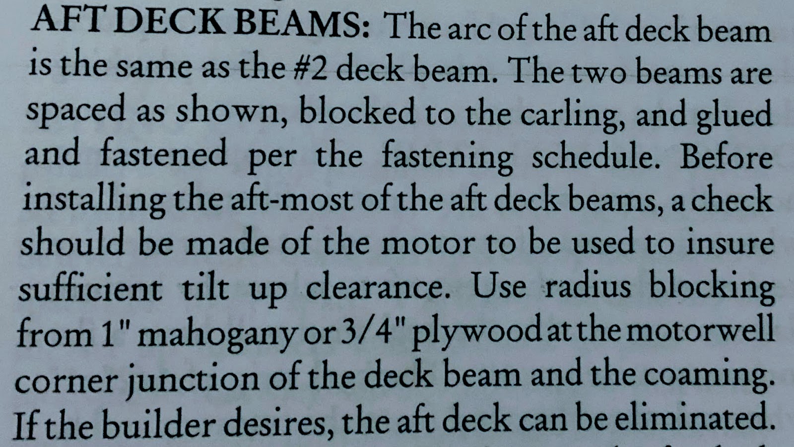
The deck beam curves were cut with a jigsaw after which their exact positions on the boat were determined. I was recommended to leave at least 400mm between the transom and the rearmost deck beam to allow room for the engine to be tilted up. Some of the compound angles made cutting the deck beams accurately to size a challenge. I am beginning to rely more and more on my angle grinder with sanding disk to trim wood quickly and easily to size. The angle grinder is such a useful tool! You need a dust mask when using it!
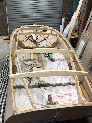 |
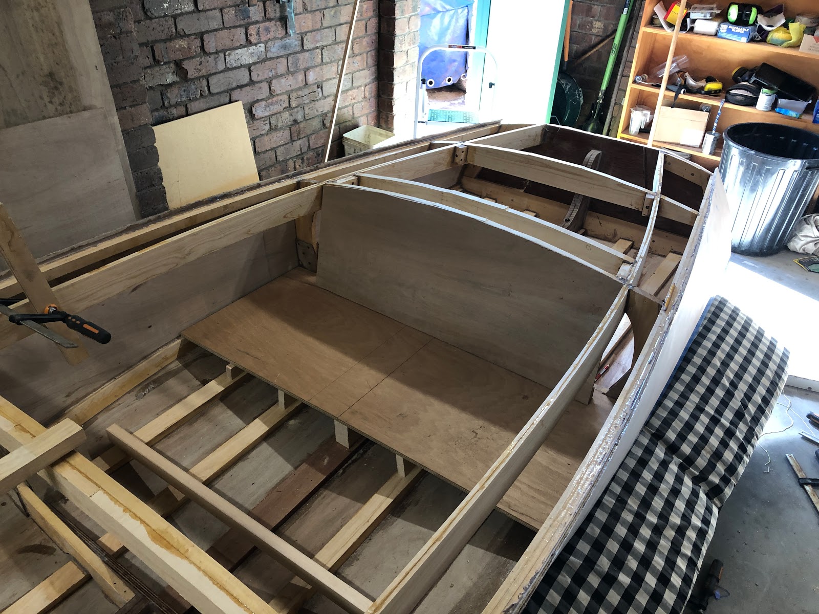
| Laying out deck beams in position |
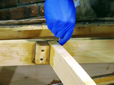
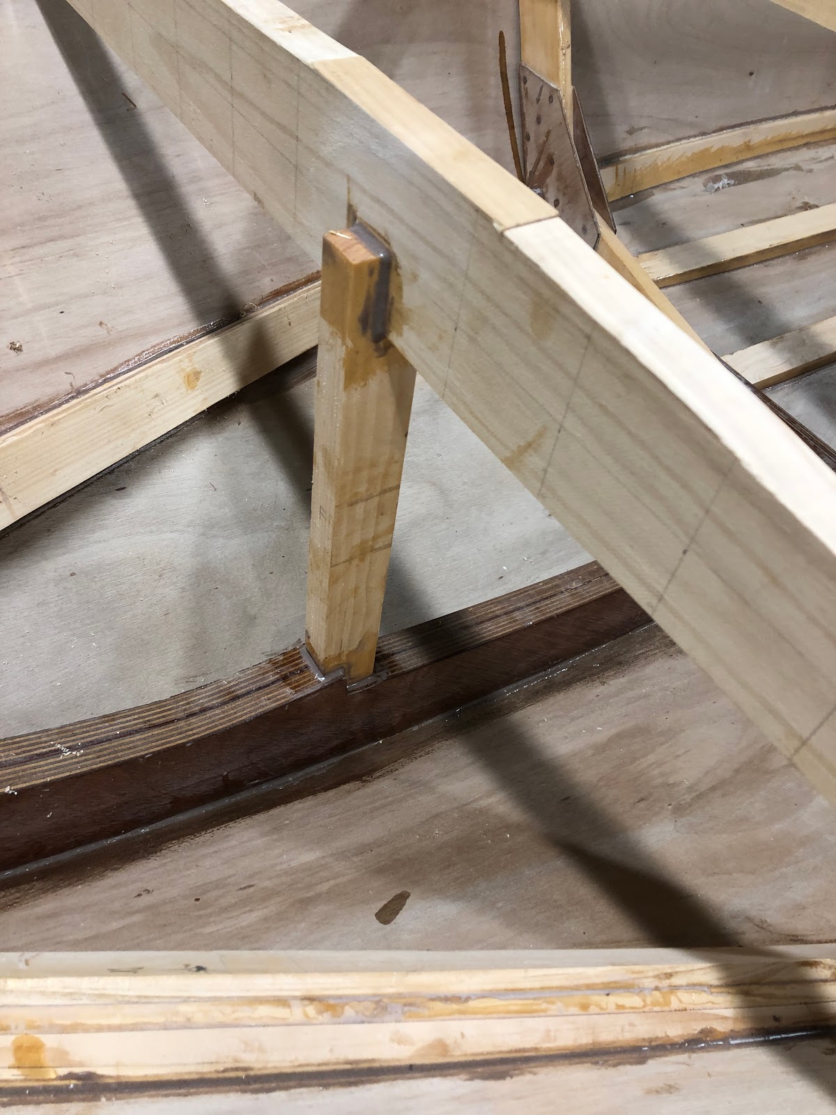
The front deck beam was supported by blocking to the sheer and an upright from the stem.
 |
| Deck beam and vertical support |
 |
| Vertical support |
 |
| Front deck beam with blocking to sheer |
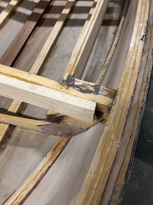
There were two deck beams installed in the vicinity of frame 1. One deck beam is angled for the seat (left in picture below) and the other will form part of the hatch structure.
 |
| Deck beams for seat and hatch |
 |
Blocking for seat and hatch deck beams
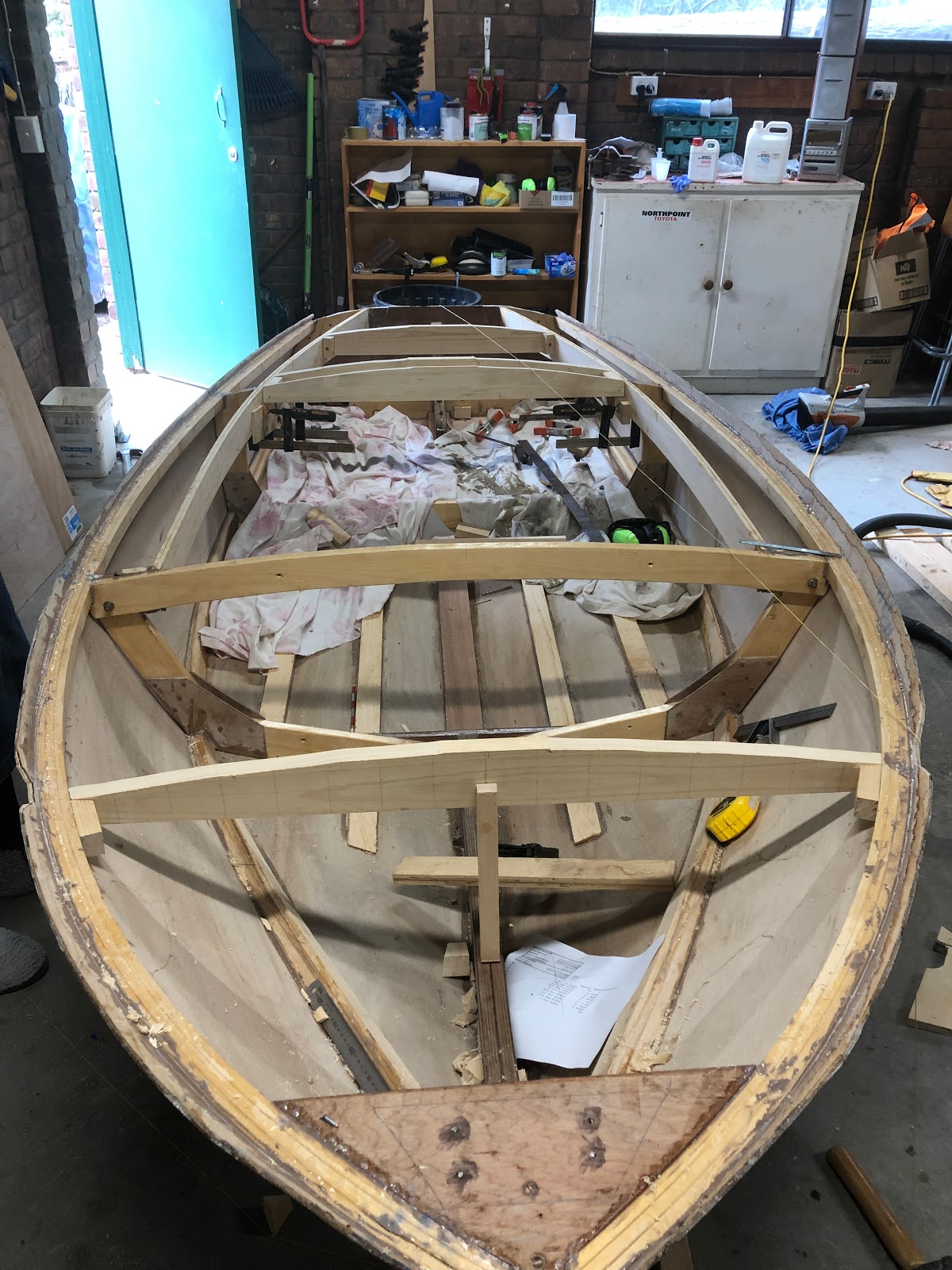
 |
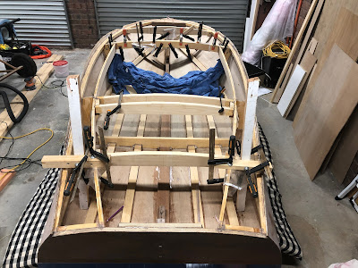
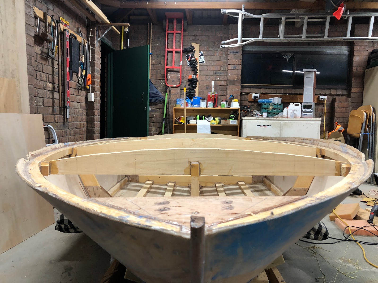
| Looking from the front gives a nice perspective of the curve of the deck. |
|
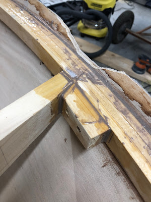
Another piece of wood was added to the deck beam on frame 2 for added strength. These frames get notched for the deck battens and therefore loose some of their strength.
 |
| Frame 2 deck beam strengthening |
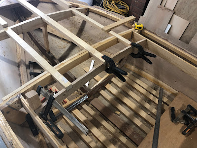
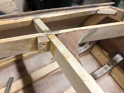
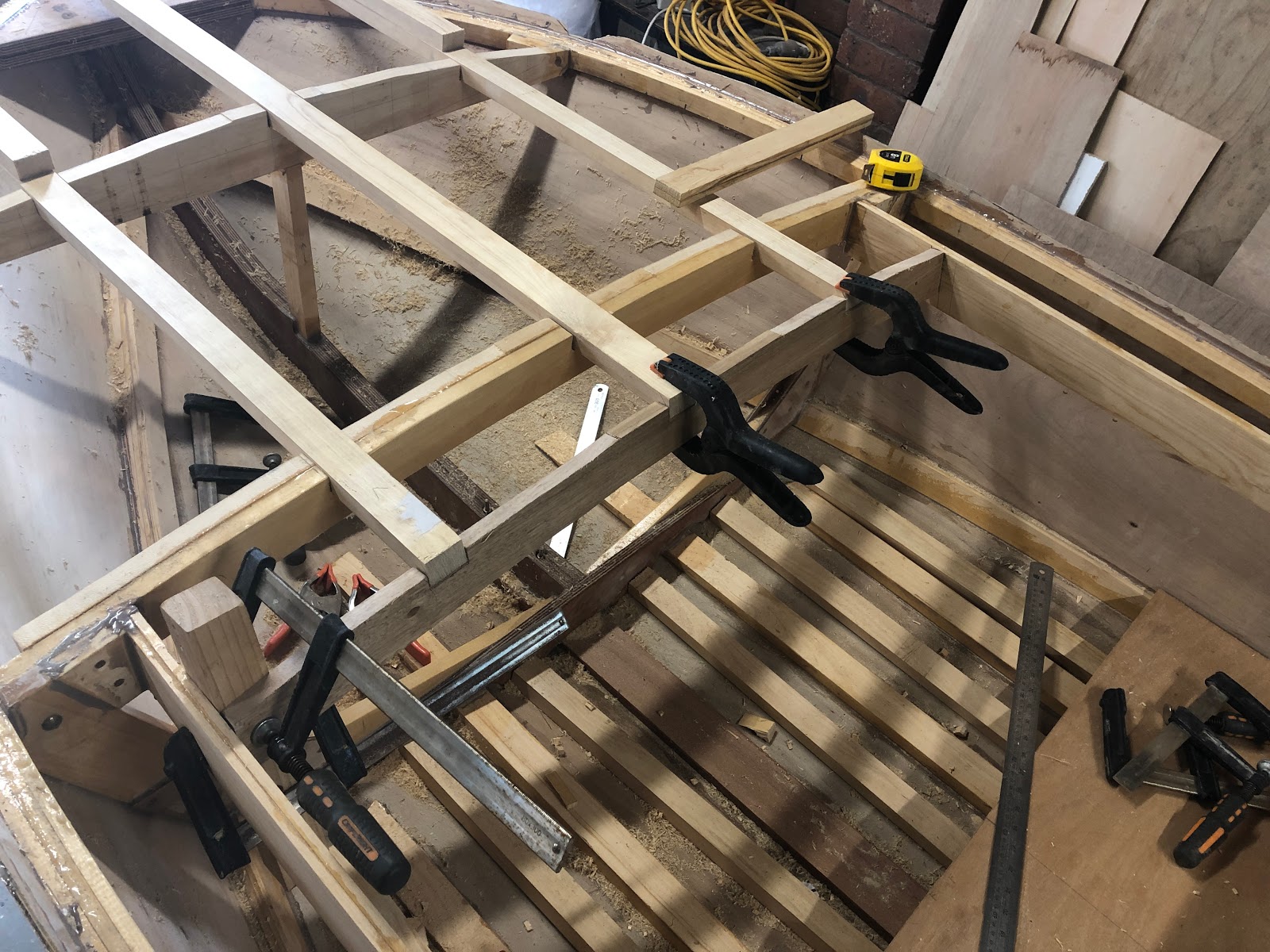
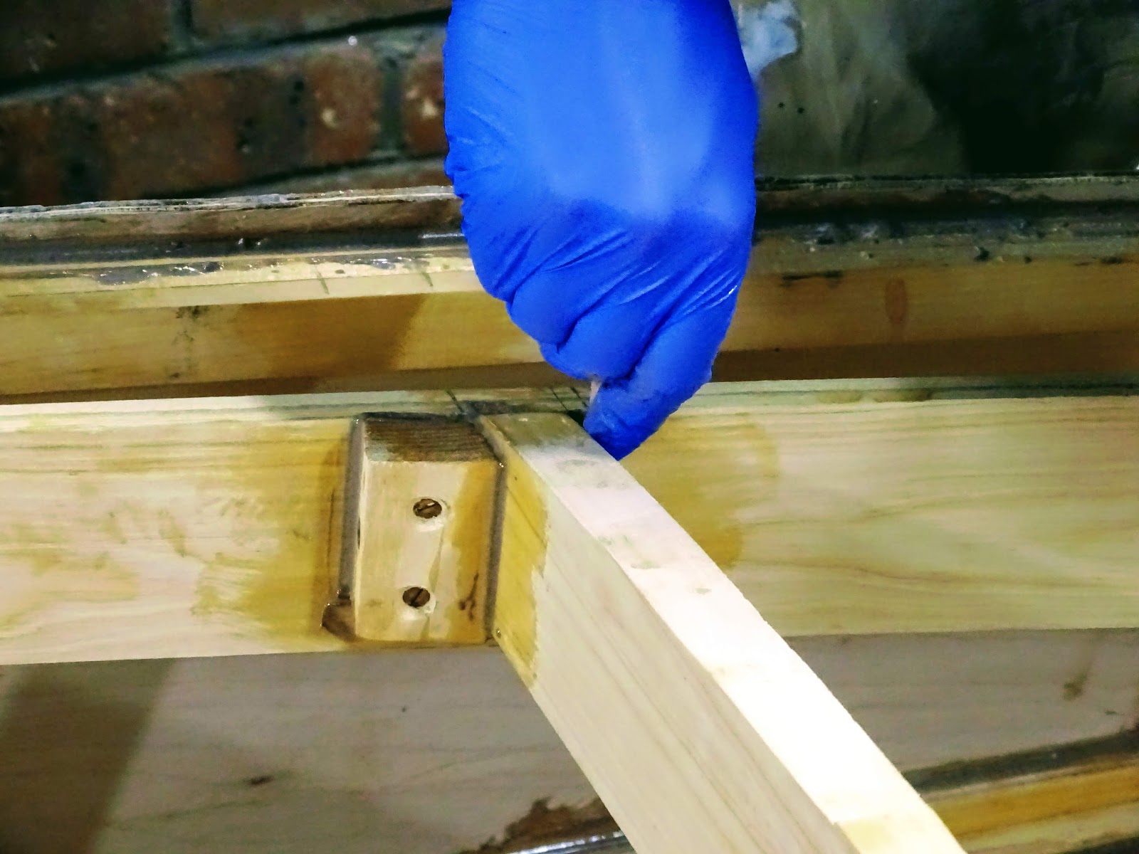
The glue-up of the rear deck beams was a bit tricky because I did not bother to create blocking for the 2 deck beam segments either side of the coaming. Hence in the image below there is some complicated clamping going on.
 |
| Epoxying the deck beams in position |
I have a tendency to underestimate how long it takes to do glue-ups. Mixing epoxy, doing neat fillets and cleaning off excess epoxy it quite time consuming.
 |
| Epoxying the deck beam in place. |
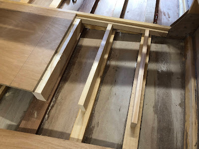
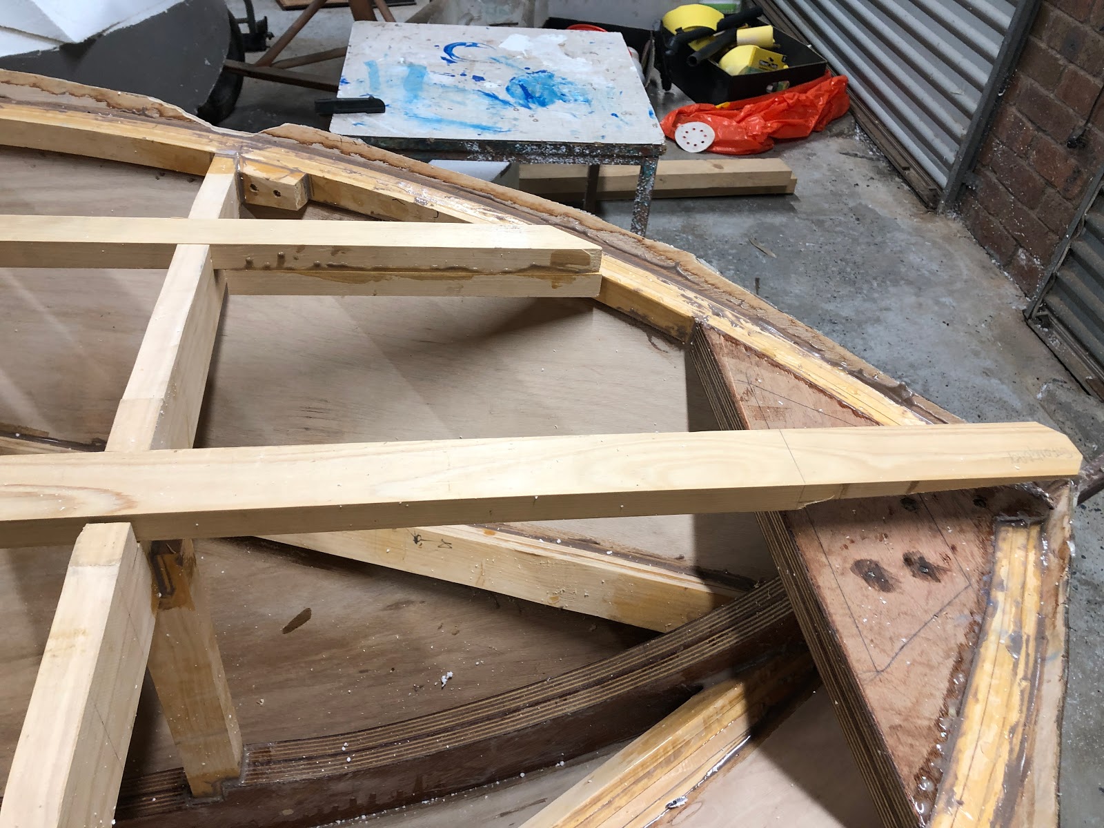
I used a router free-hand to notch out the deck beams for the deck battens and strongback(center longitudinal). An auxiliary dash beam to which the actual dash will attach was installed. It was a bit of playing around to get the dash in what I thought was an appropriate position and angle for the steering.
 |
| Auxiliary dash beam, strongback and deck battens |
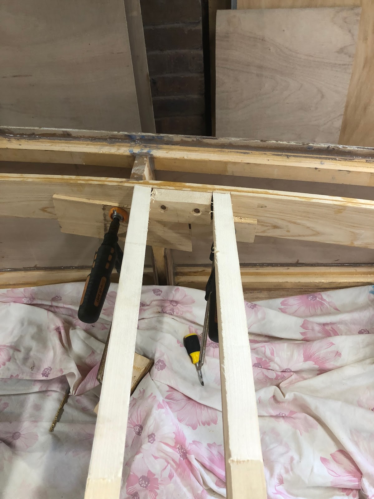
The deck battens were too thick to be able to bend down to the sheer so I laminated another piece of wood under them to eliminate the need to bend them. The plan is to simply plane (or angle grind) them down to the curve of the deck. The strongback bends down to the breast-hook relatively easily. The strongback was tapered to fit the breast-hook in about 1 minute using the angle grinder. I am not gluing the battens and strongback in place yet because I need to add flotation foam to the front of the boat.
 |
| Deck batten and strongback |
Extra pieces of hoop pine were added between each of the battens on the floor of the boat. This is to act as flooring. I still need to shape these extra floor battens to the curve of the hull which will be another angle grinder job. A seat was created by resting a piece of plywood on the chine timbers and then adding supports to the keel and battens. The supports are perpendicular to the battens and angled where they meet the seat. In hindsight it would have been more aesthetically pleasing to have them perpendicular to the seat. I am considering adding a decorative piece of wood to the front of the seat to hide the supports.
 |
| Seat and flooring |
The seat is in two parts, There is also a support for the seat along frame 1.
 |
| Seat in two parts |
An angled piece of wood was cut and glued in place to support the back rest of the seat.
 |
| Backrest support |
 |
| The finished seat structure. |
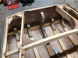
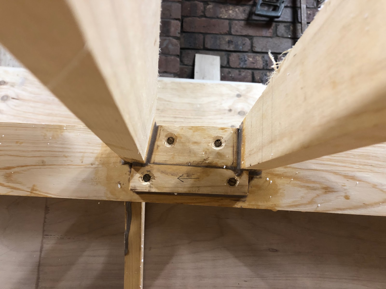
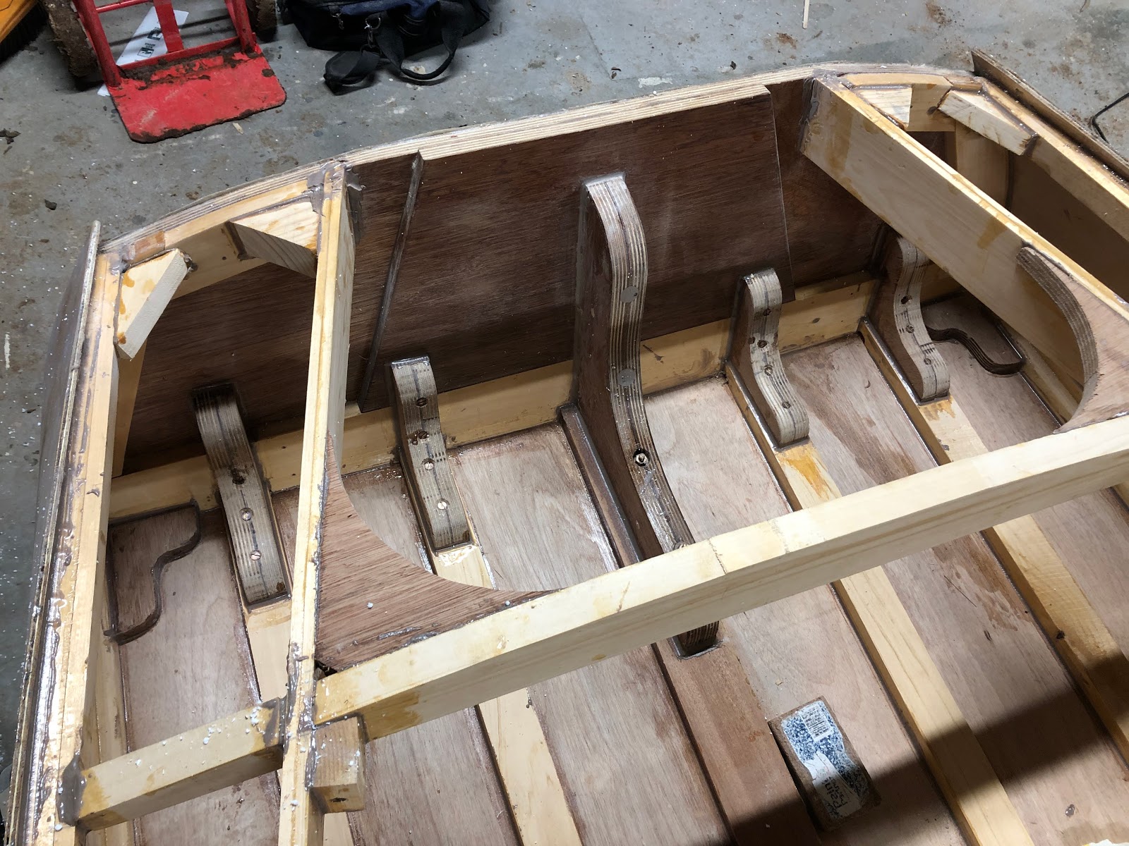
As I am intending to power the boat with a 20 horse power engine, I decided to beef up the transom with some more transom knees. These transom knees are scaled down versions of the larger knee and should serve to transfer the force of the engine onto the battens without any excessive stress concentrations. They are each held in place with epoxy and silicon bronze screws.
 |
| Transom knees |
The router table and flush trim router bit was used to create the transom knees.
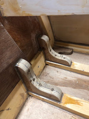 |
| Transom knees |
Some supports were also added to strengthen the joints between the transom-sheer and transom-coaming.
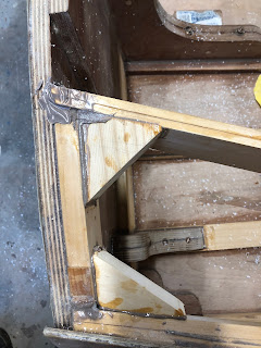 |
| Sheer and coaming supports |
Curved bracing was added between the coaming and the rear-most deck beam.
 |
| Deck beam and coaming bracing |
Building the frame was a lot of fun and it felt like I was achieving a lot!
The next step is to determine how much buoyancy foam needs to be installed and this will be followed by sanding the interior of the hull and giving it a good coat of epoxy.
Cheers!


