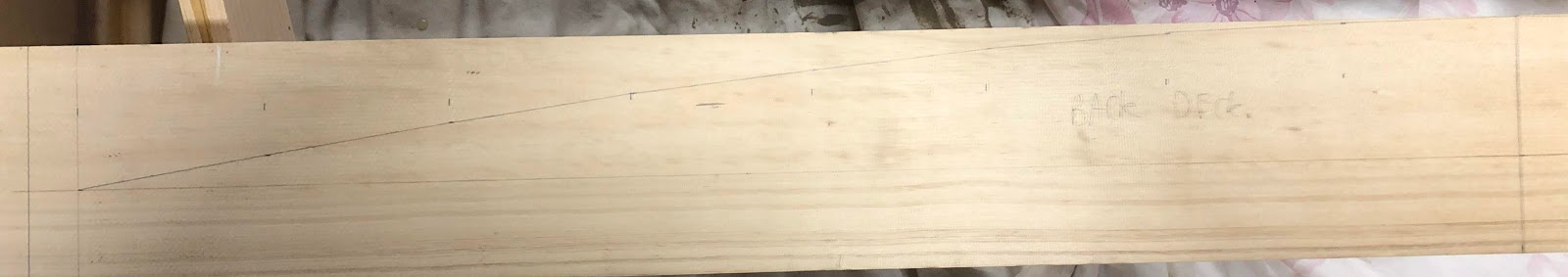
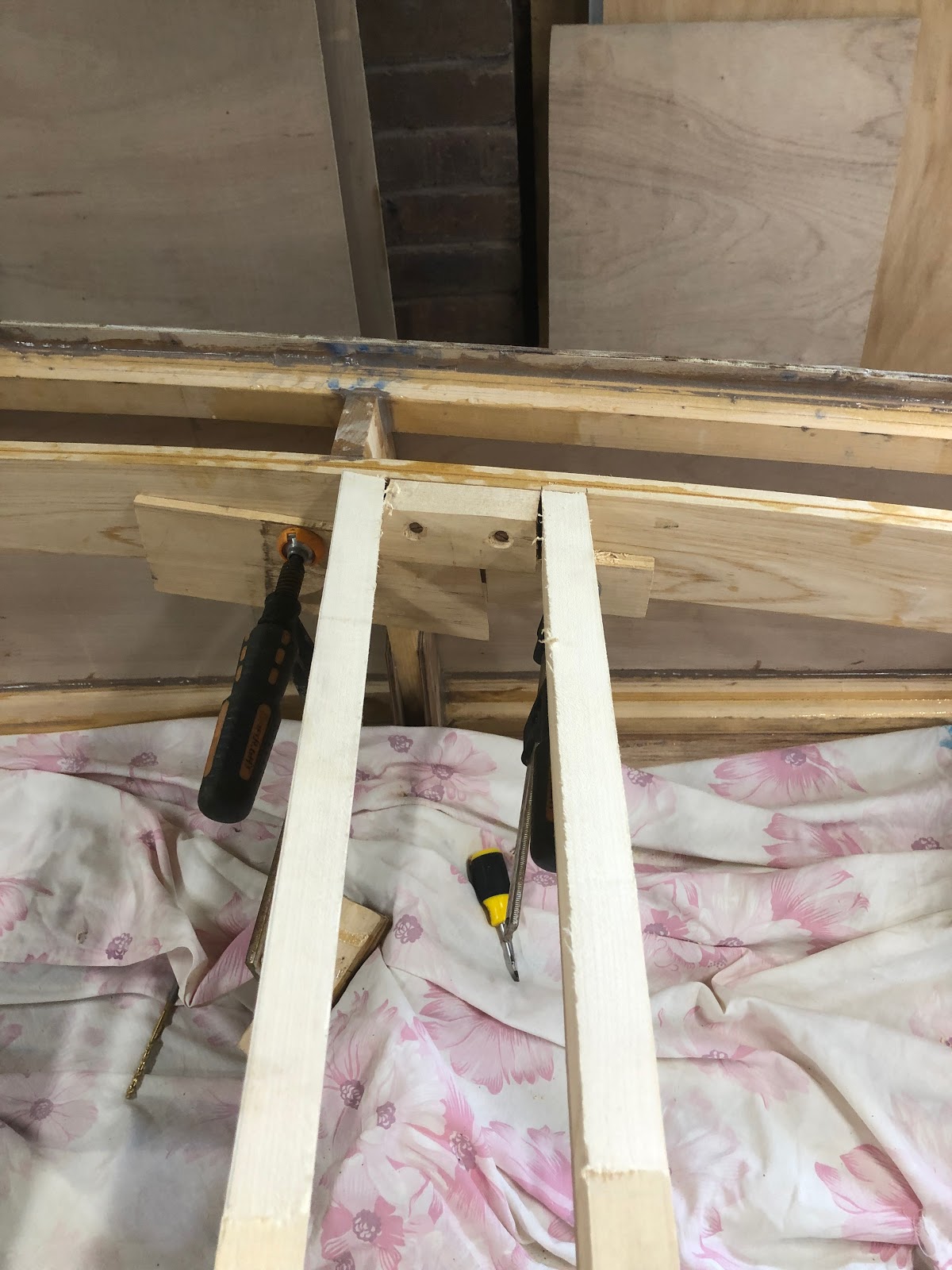
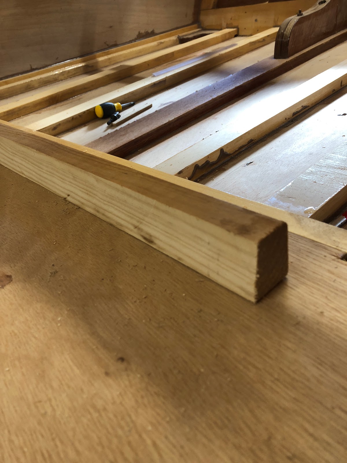
After installing the coaming and determining the deck beam curves, I marked out and cut the deck beams.
Marking out one of the deck beams
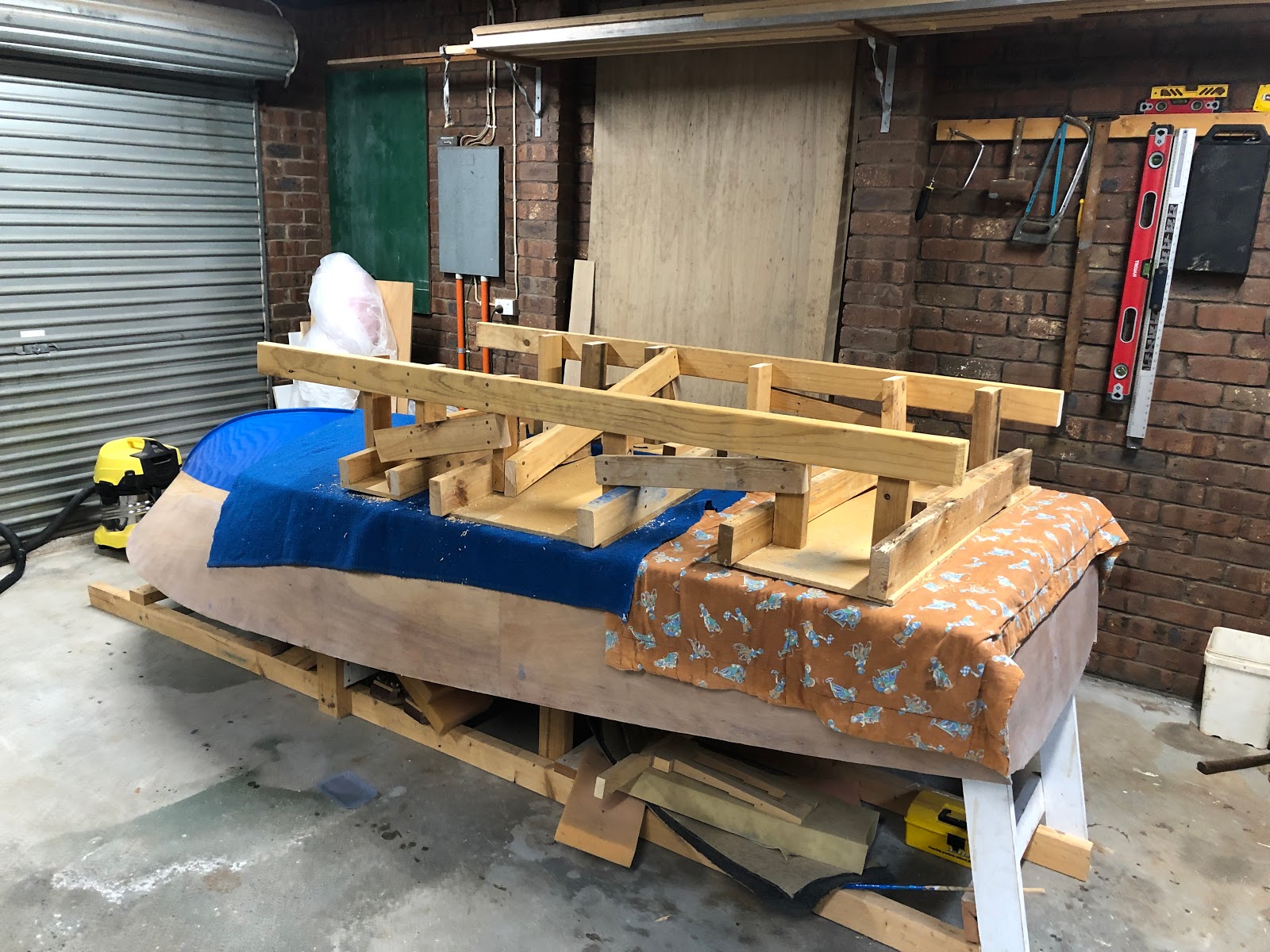
The deck beam curves were cut with a jigsaw after which their exact positions on the boat were determined. I was recommended to leave at least 400mm between the transom and the rearmost deck beam to allow room for the engine to be tilted up. Some of the compound angles made cutting the deck beams accurately to size a challenge. I am beginning to rely more and more on my angle grinder with sanding disk to trim wood quickly and easily to size. The angle grinder is such a useful tool! You need a dust mask when using it!
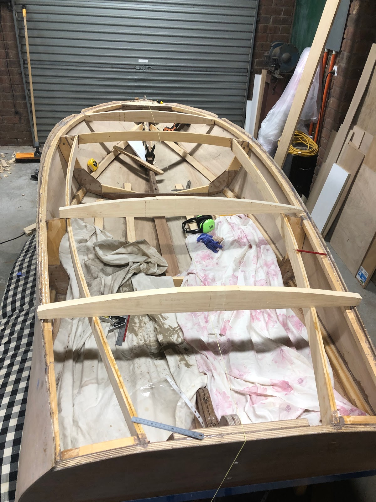
Laying out deck beams in position
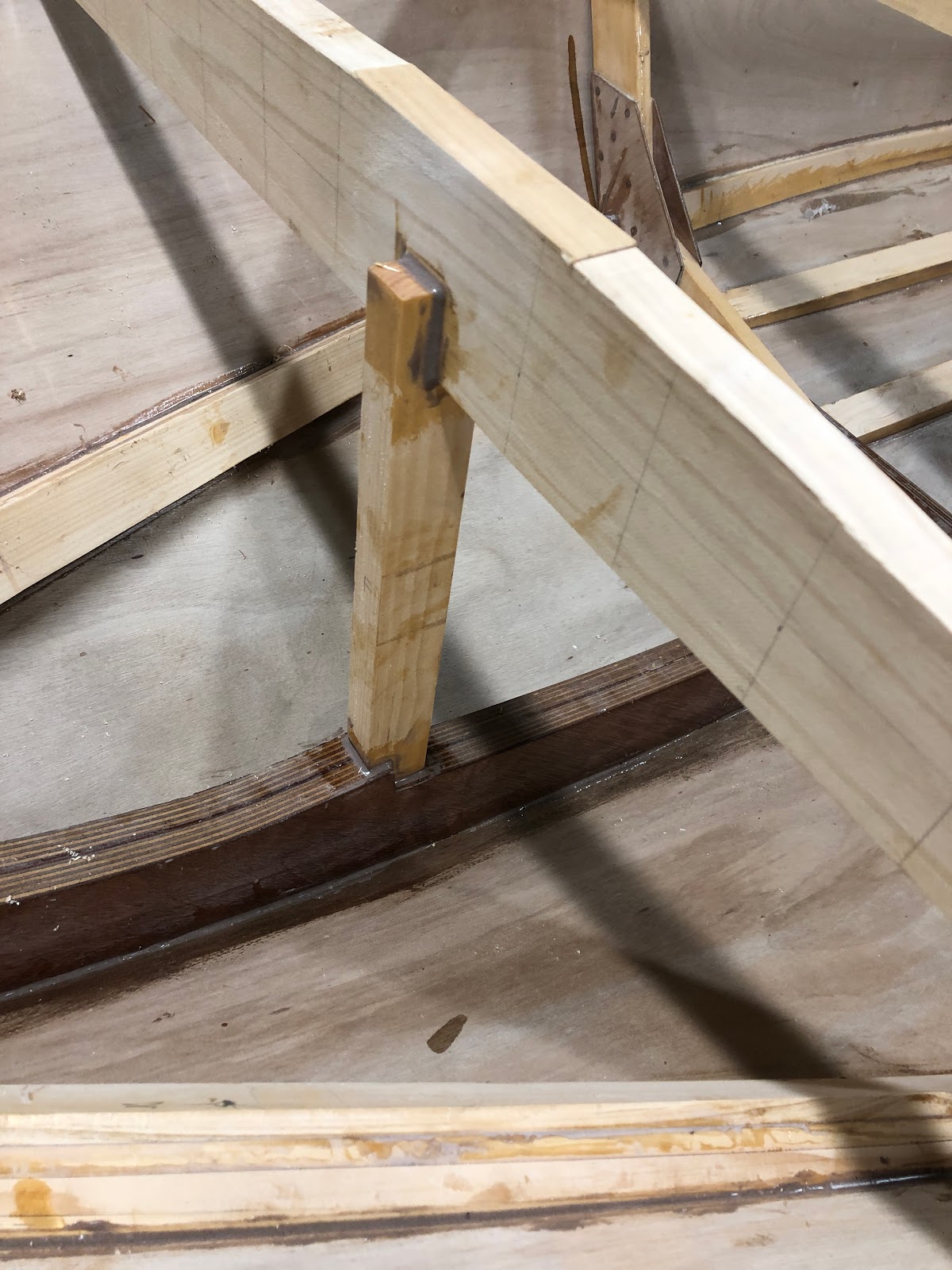
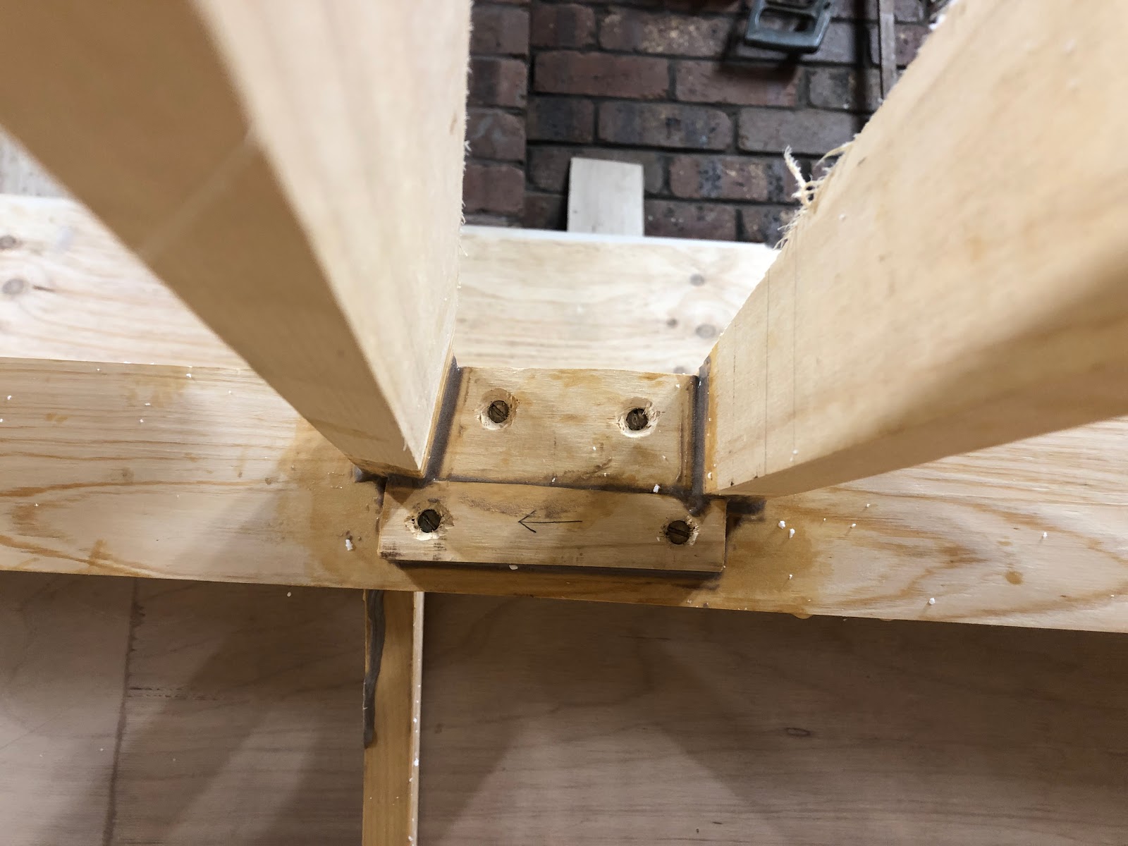
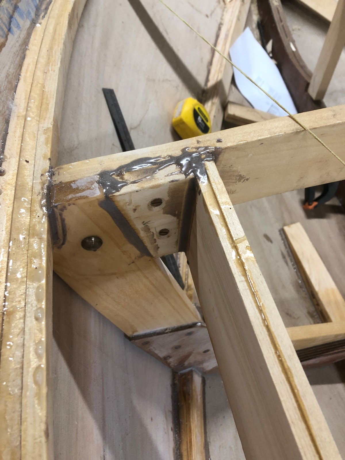
The front deck beam was supported by blocking to the sheer and an upright from the stem.
Deck beam and vertical support
Vertical support
Front deck beam with blocking to sheer
There were two deck beams installed in the vicinity of frame 1. One deck beam is angled for the seat (left in picture below) and the other will form part of the hatch structure.
Deck beams for seat and hatch
Blocking for seat and hatch deck beams
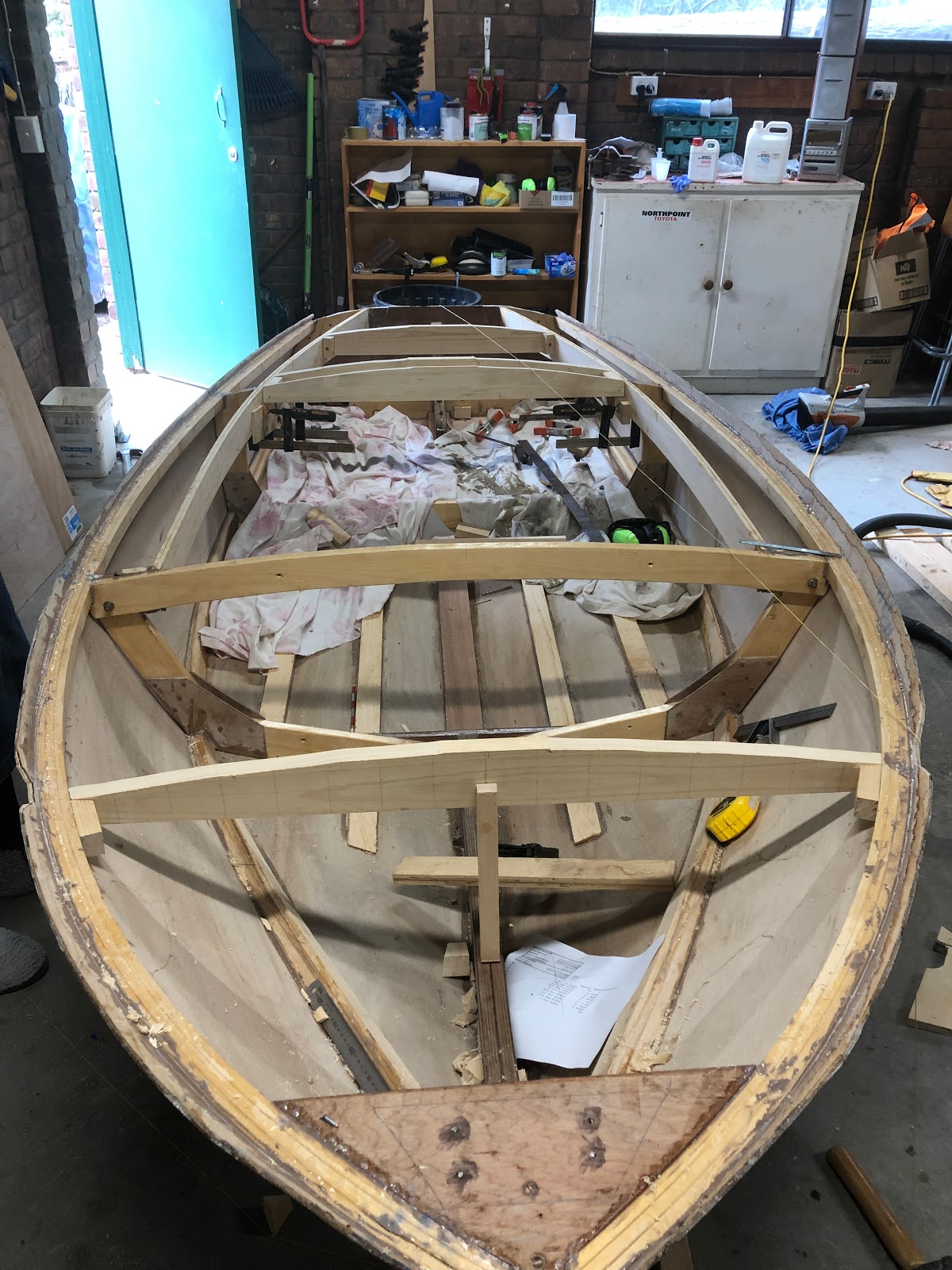
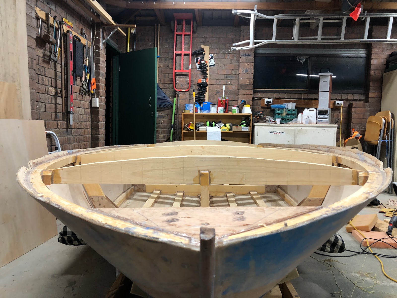
Looking from the front gives a nice perspective of the curve of the deck.
Another piece of wood was added to the deck beam on frame 2 for added strength. These frames get notched for the deck battens and therefore loose some of their strength.
Frame 2 deck beam strengthening
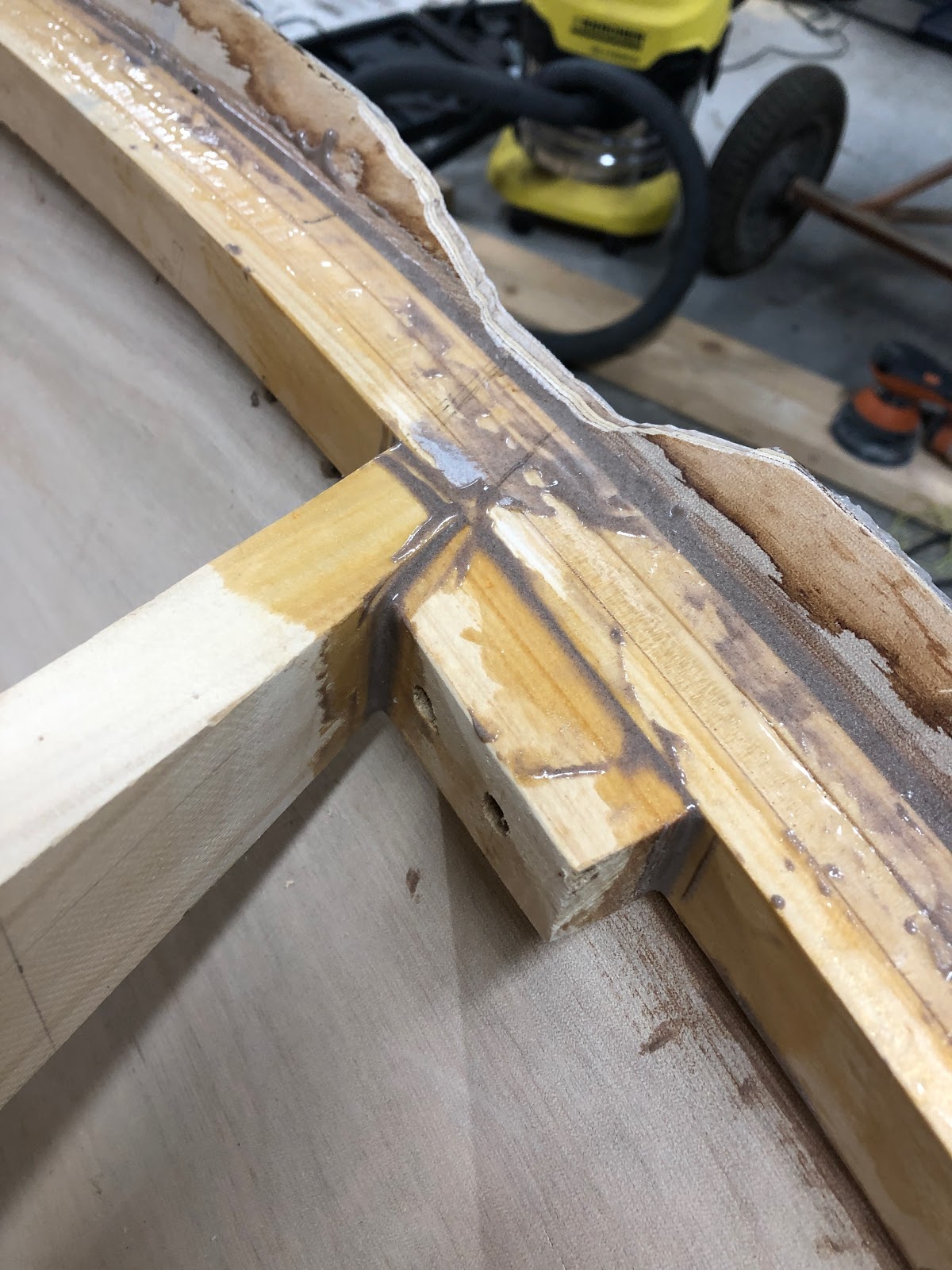
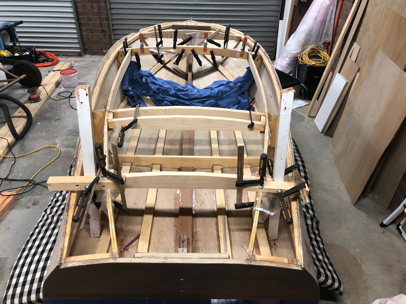
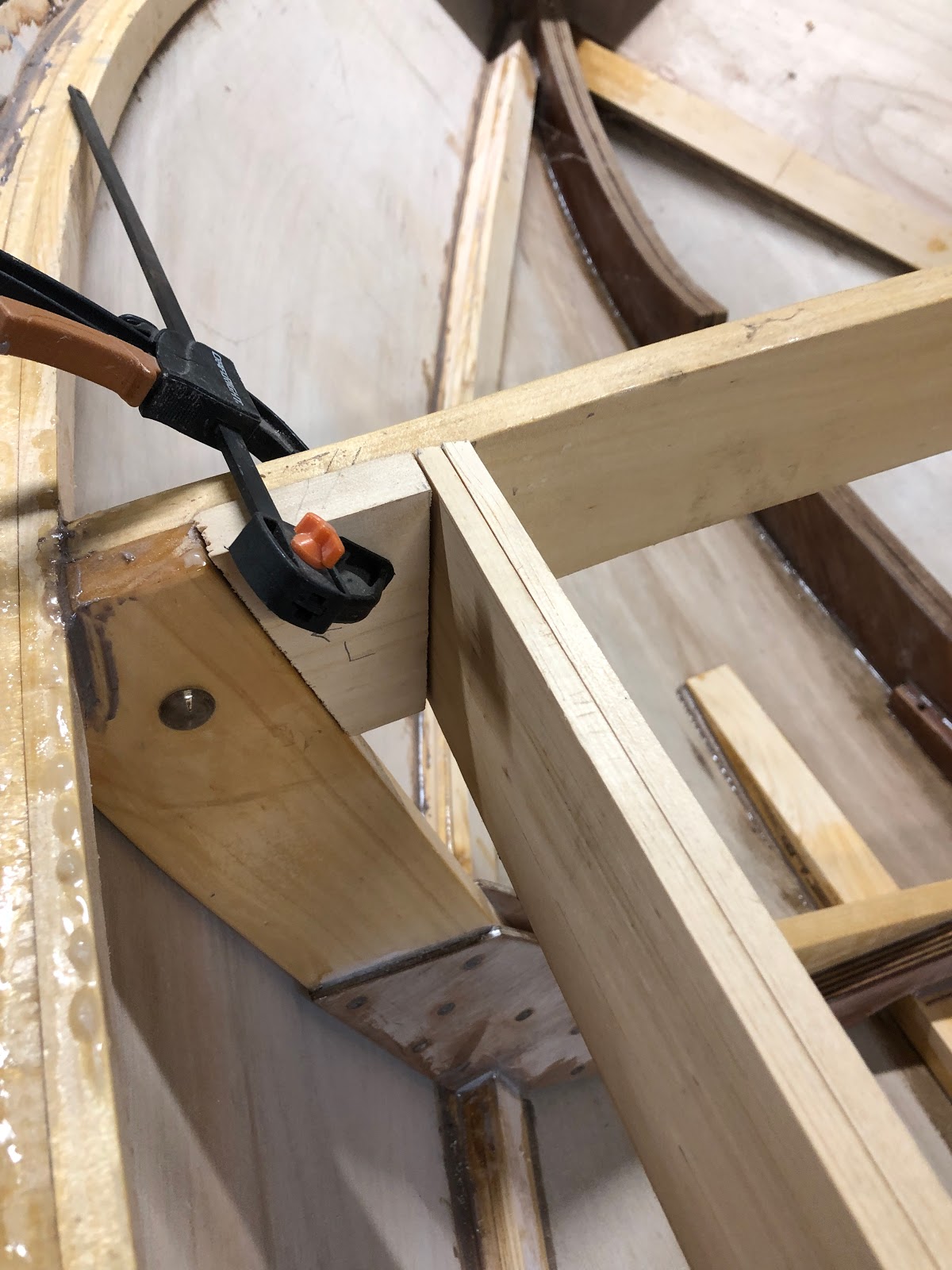
The glue-up of the rear deck beams was a bit tricky because I did not bother to create blocking for the 2 deck beam segments either side of the coaming. Hence in the image below there is some complicated clamping going on.
Epoxying the deck beams in position
I have a tendency to underestimate how long it takes to do glue-ups. Mixing epoxy, doing neat fillets and cleaning off excess epoxy it quite time consuming.
Epoxying the deck beam in place.
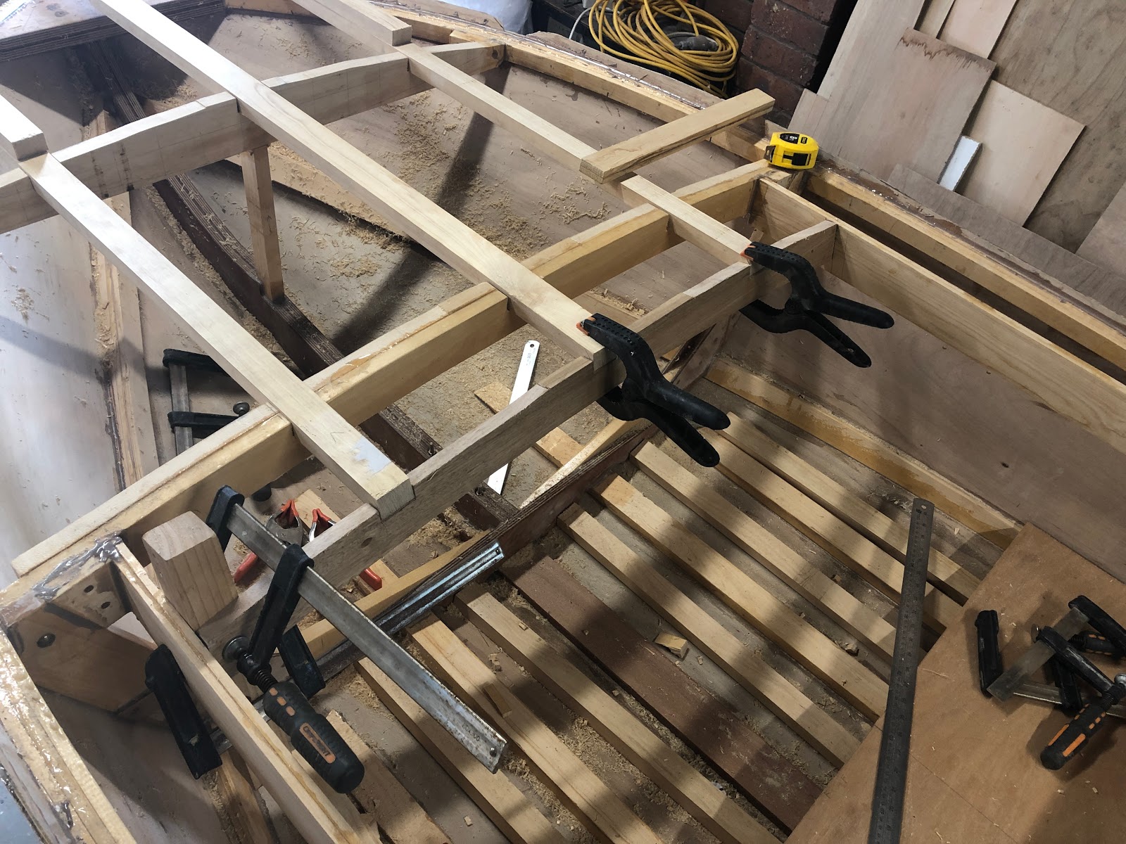
I used a router free-hand to notch out the deck beams for the deck battens and strongback(center longitudinal). An auxiliary dash beam to which the actual dash will attach was installed. It was a bit of playing around to get the dash in what I thought was an appropriate position and angle for the steering.
Auxiliary dash beam, strongback and deck battens
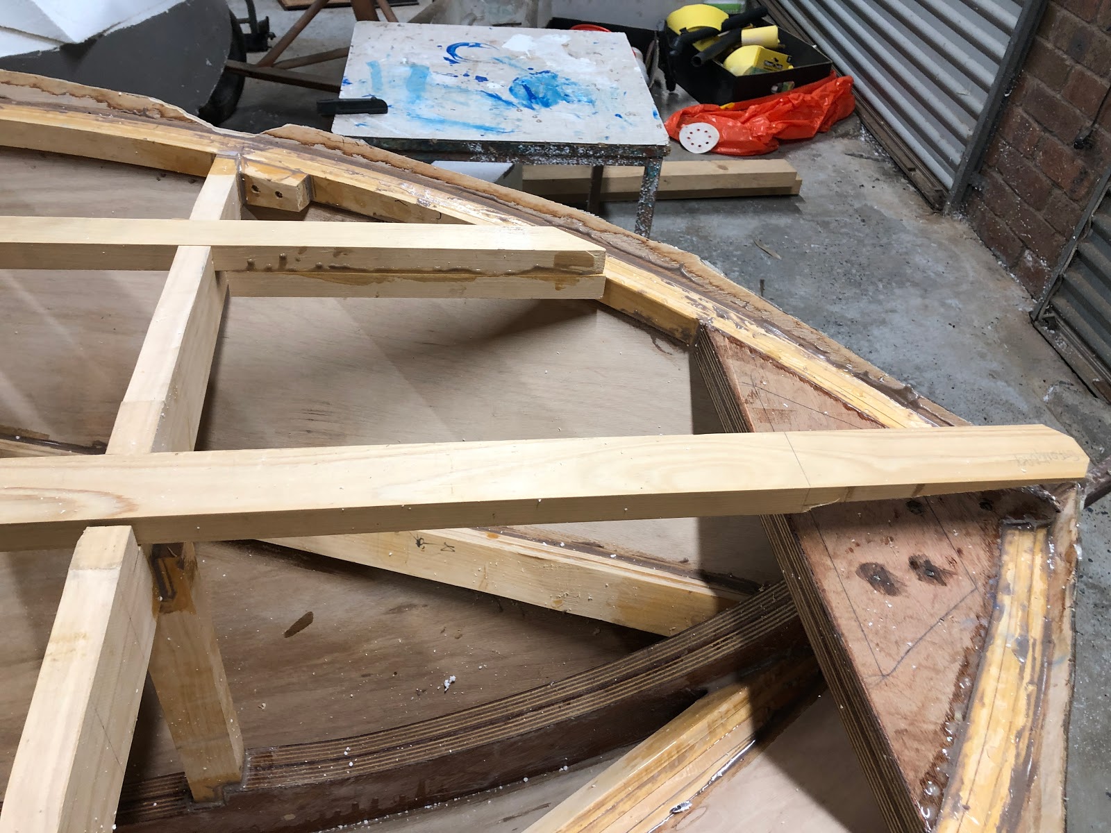
The deck battens were too thick to be able to bend down to the sheer so I laminated another piece of wood under them to eliminate the need to bend them. The plan is to simply plane (or angle grind) them down to the curve of the deck. The strongback bends down to the breast-hook relatively easily. The strongback was tapered to fit the breast-hook in about 1 minute using the angle grinder. I am not gluing the battens and strongback in place yet because I need to add flotation foam to the front of the boat.
Deck batten and strongback
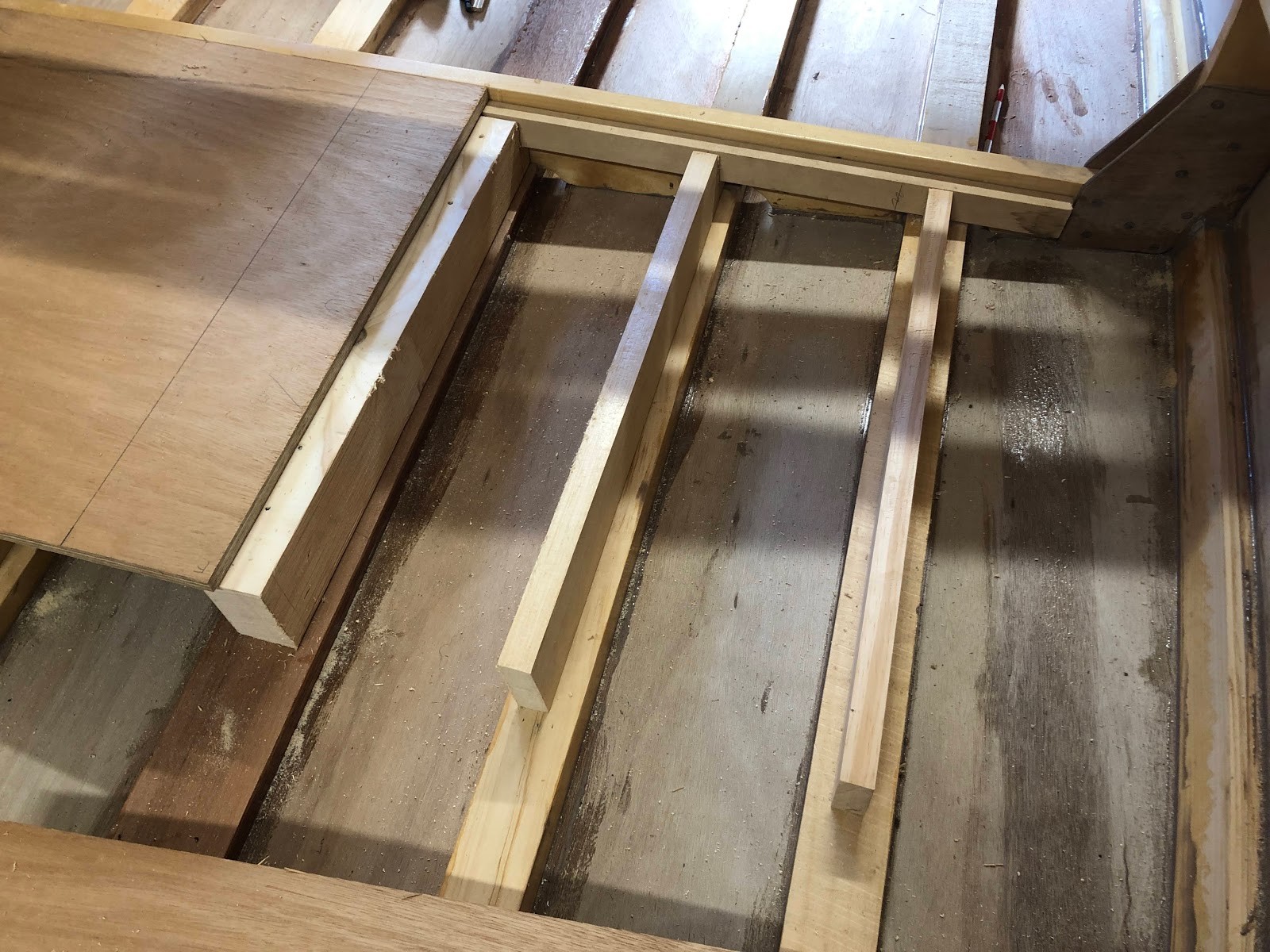
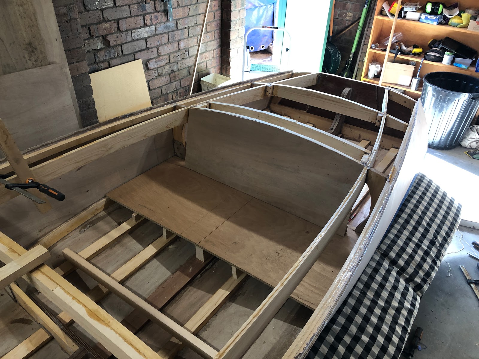
Extra pieces of hoop pine were added between each of the battens on the floor of the boat. This is to act as flooring. I still need to shape these extra floor battens to the curve of the hull which will be another angle grinder job. A seat was created by resting a piece of plywood on the chine timbers and then adding supports to the keel and battens. The supports are perpendicular to the battens and angled where they meet the seat. In hindsight it would have been more aesthetically pleasing to have them perpendicular to the seat. I am considering adding a decorative piece of wood to the front of the seat to hide the supports.
Seat and flooring
The seat is in two parts, There is also a support for the seat along frame 1.
Seat in two parts
An angled piece of wood was cut and glued in place to support the back rest of the seat.
Backrest support
The finished seat structure.
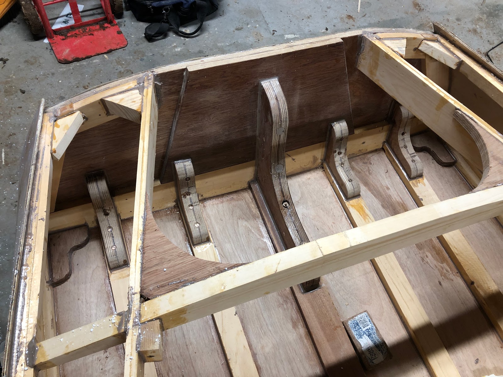
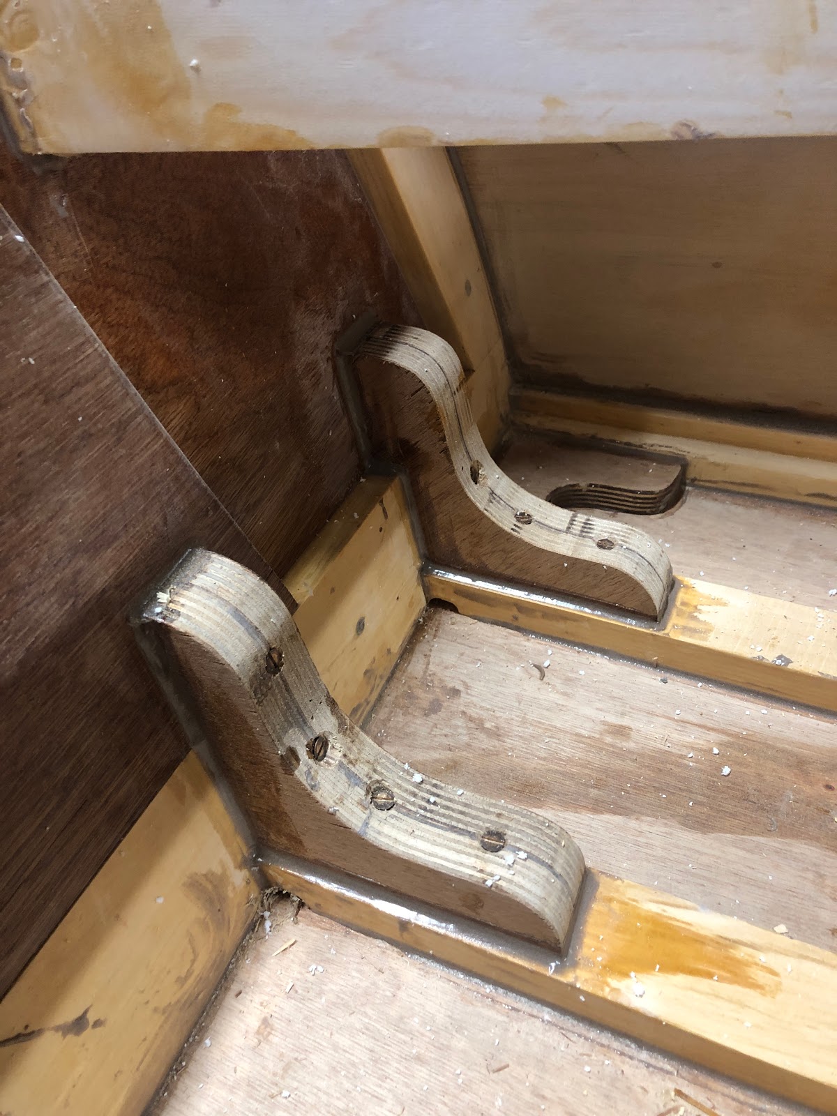
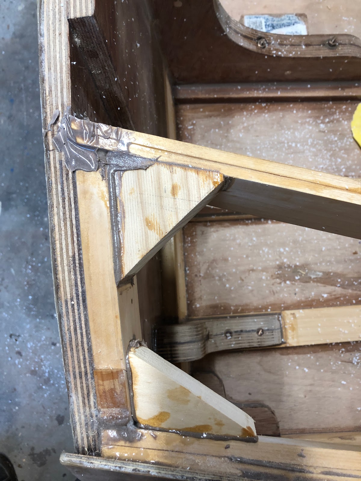
As I am intending to power the boat with a 20 horse power engine, I decided to beef up the transom with some more transom knees. These transom knees are scaled down versions of the larger knee and should serve to transfer the force of the engine onto the battens without any excessive stress concentrations. They are each held in place with epoxy and silicon bronze screws.
Transom knees
The router table and flush trim router bit was used to create the transom knees.
Transom knees
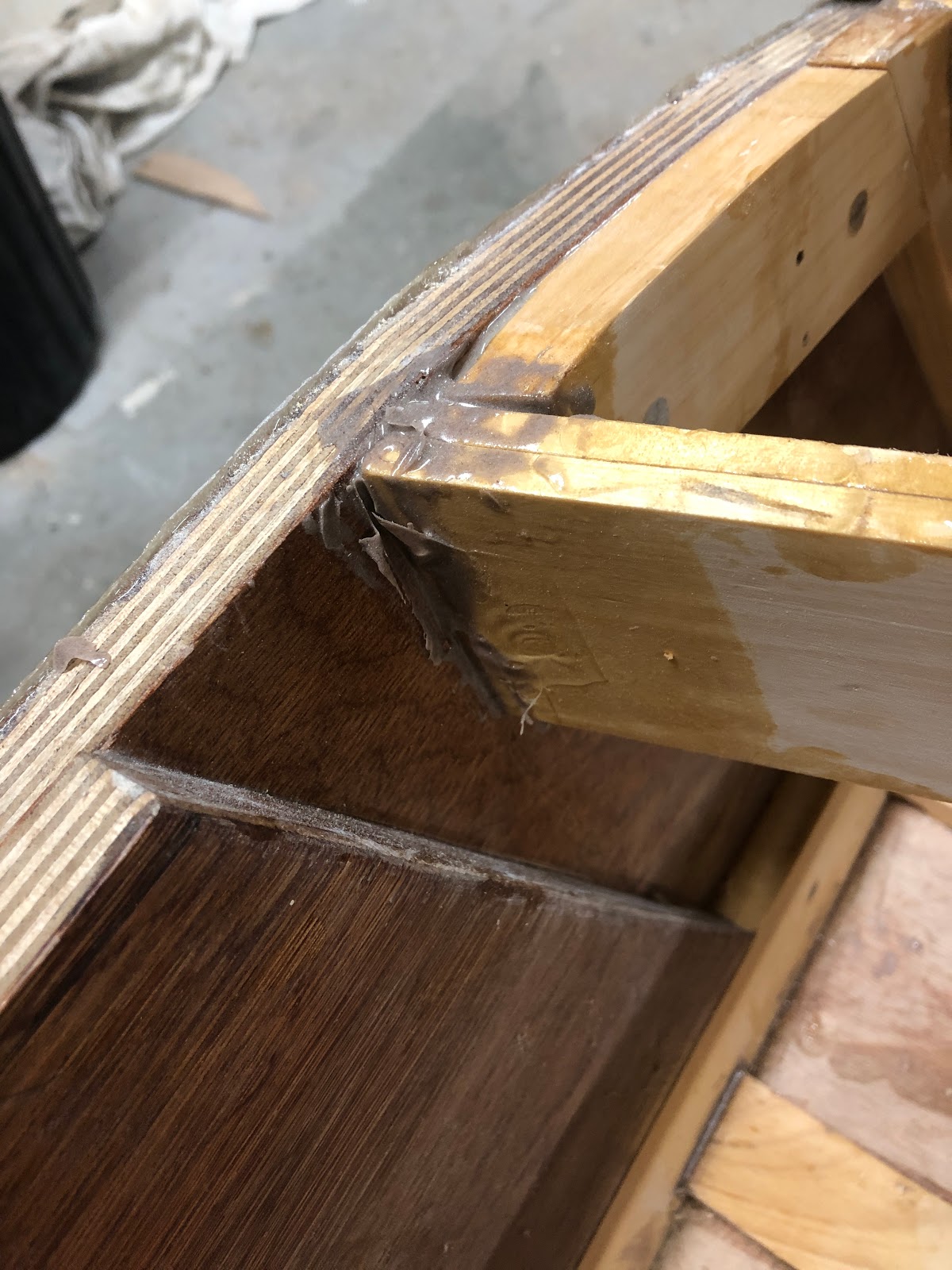
Some supports were also added to strengthen the joints between the transom-sheer and transom-coaming.
Sheer and coaming supports
Curved bracing was added between the coaming and the rear-most deck beam.
Deck beam and coaming bracing
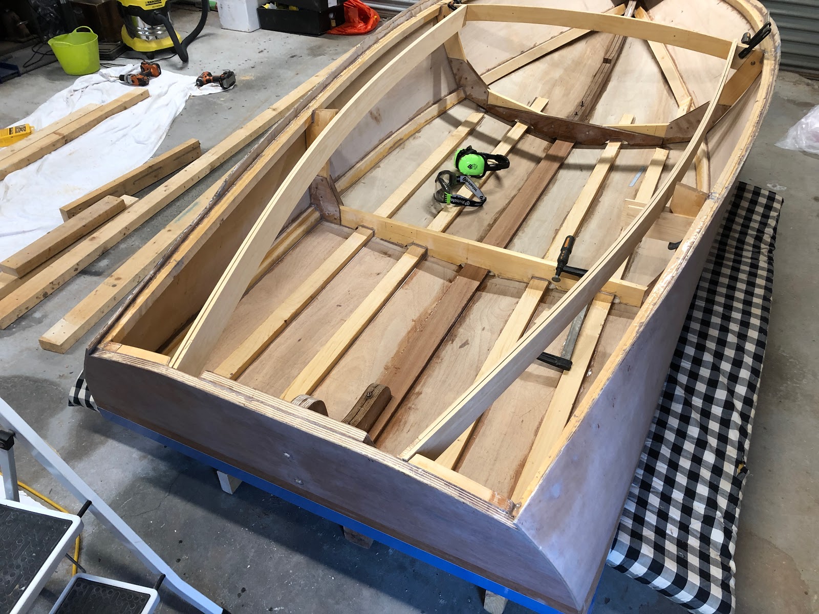
Building the frame was a lot of fun and it felt like I was achieving a lot!
The next step is to determine how much buoyancy foam needs to be installed and this will be followed by sanding the interior of the hull and giving it a good coat of epoxy.
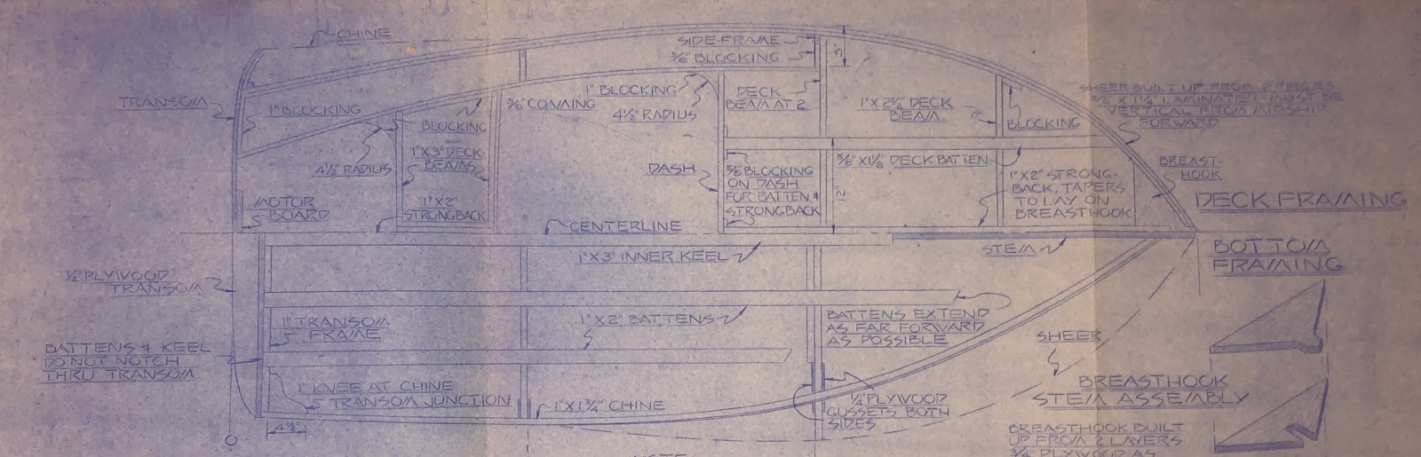
Before I ordered the timber for the internals of the boat, I drew the following sketch showing the lumber that would be needed.
Sketch of interior lumber
There are quite a number of pieces of wood (in green) going across the width of the boat which I have called 'deck beams'. These pieces of wood cannot be straight. They need to have curves that are consistent with the curves defined on the plans for the the Transom, Frame 1 and Frame 2.
Frames & Transom
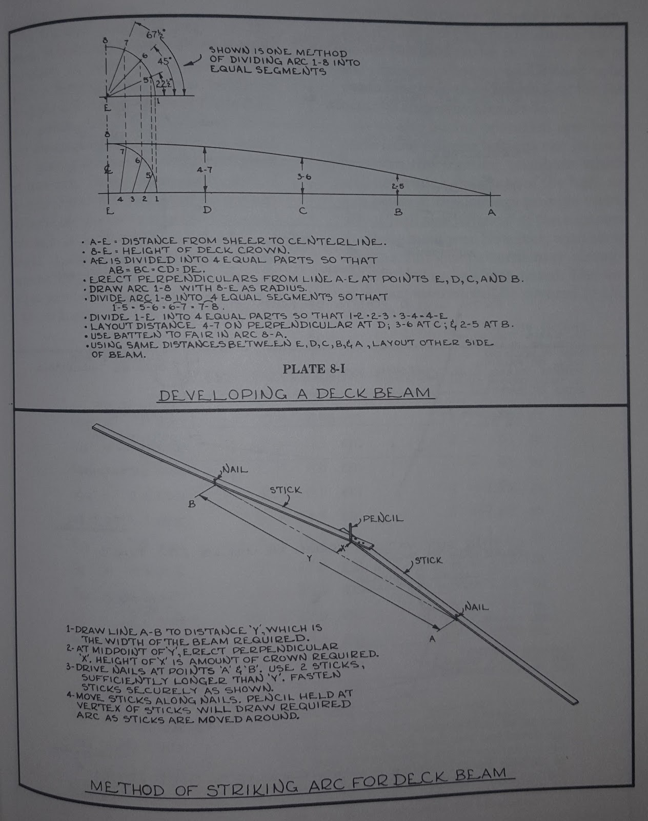
The quandary is how to know what curves to cut. The simplest solution would be to simply copy Frame 2 for the forward deck beams and then 'eyeball' the aft beams based on Frame 1 and the Transom. I suspect this 'eyeballing' method would have been fine especially given it all needs faring anyway and that epoxy can fill gaps admirably. I wasn't satisfied with that approach and wanted a more analytical way of developing the deck beams. Glen L Witt's book, 'Boat Building With Plywood' gives some methods of developing deck beams.
Plate 8-J from 'Boatbuilding With Plywood'
Initially, I considered making the jig shown in the bottom half of the image above but I decided it would be easier to do the maths to work out the formula for the curve the jig would scribe. The development of the formula is shown below.
I think maths is beautiful because it can describe with infinite perfectness the truths of geometry.
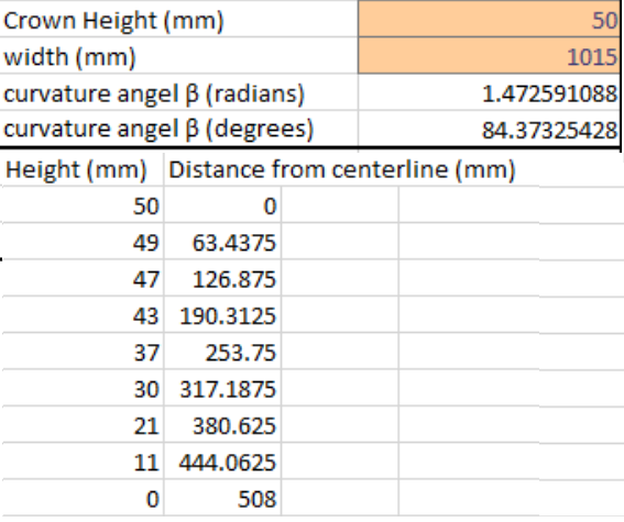
With these formulas I can now plot a deck beam for any width and any given crown.
The concept is that you have a consistent β angle across your whole deck. The crown of the deck changes as the width of the boat changes but the β angle remains the same. The curvature of the deck is defined by the β angle.
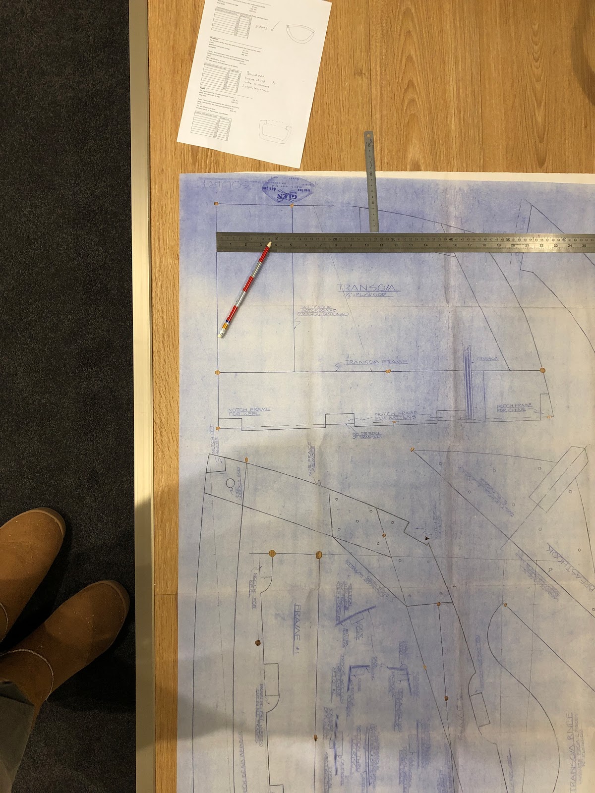
Measuring the crown and width of transom on the plans.
Using the plans, I measured the width and crown of the deck beam on Frame 2 which allowed me to calculate the β angle which will define the curve of the deck. With the β angle I could then generate a curve for any point on the deck of the boat by simply measuring the width at that point. (Obviously, at the very front of the boat the width is 0 so the height of the deck beam is zero at that point. The formula makes that clear as the term (W+2d) will equate to 0 when the width W = 0 and d therefore by necessity equals 0.)
Frame 2 was calculated to have the following crown and width.
The forward deck beam at its measured width W was then developed using the β angle of 84.7degrees and the formula above.
The Beams
I was expecting the β angle for the deck beam of Frame 2 to match the curves of both Frame 1 and the transom. This was not the case however. Furthermore, I found it difficult to find a β angle that would match the transom and Frame 1. In the end, I chose the following:
For the beam between the Transom and Frame 1
For the beam at Frame 1 (this beam will be the seat backrest)
Ironically after I finished cutting out the beams I read the instructions which say:
Pro Tip - READ THE INSTRUCTIONS!
Apart from using this analytical overkill to develop the forward most deck beam, the whole exercise was a bit pointless. BUT I like maths! I enjoyed exploring this and had some good conversations with my friend Jeremy (maths teacher) about it. I also used the geometry explained in plate 8-I above to develop the deck beams. This method was much simpler to calculate. I suspect both methods yield the same geometry. The results were slightly different in excel but I expect that is due to rounding errors in the trig functions. I would like to check to see if they are the same but I would like even more to just keep working on the build.
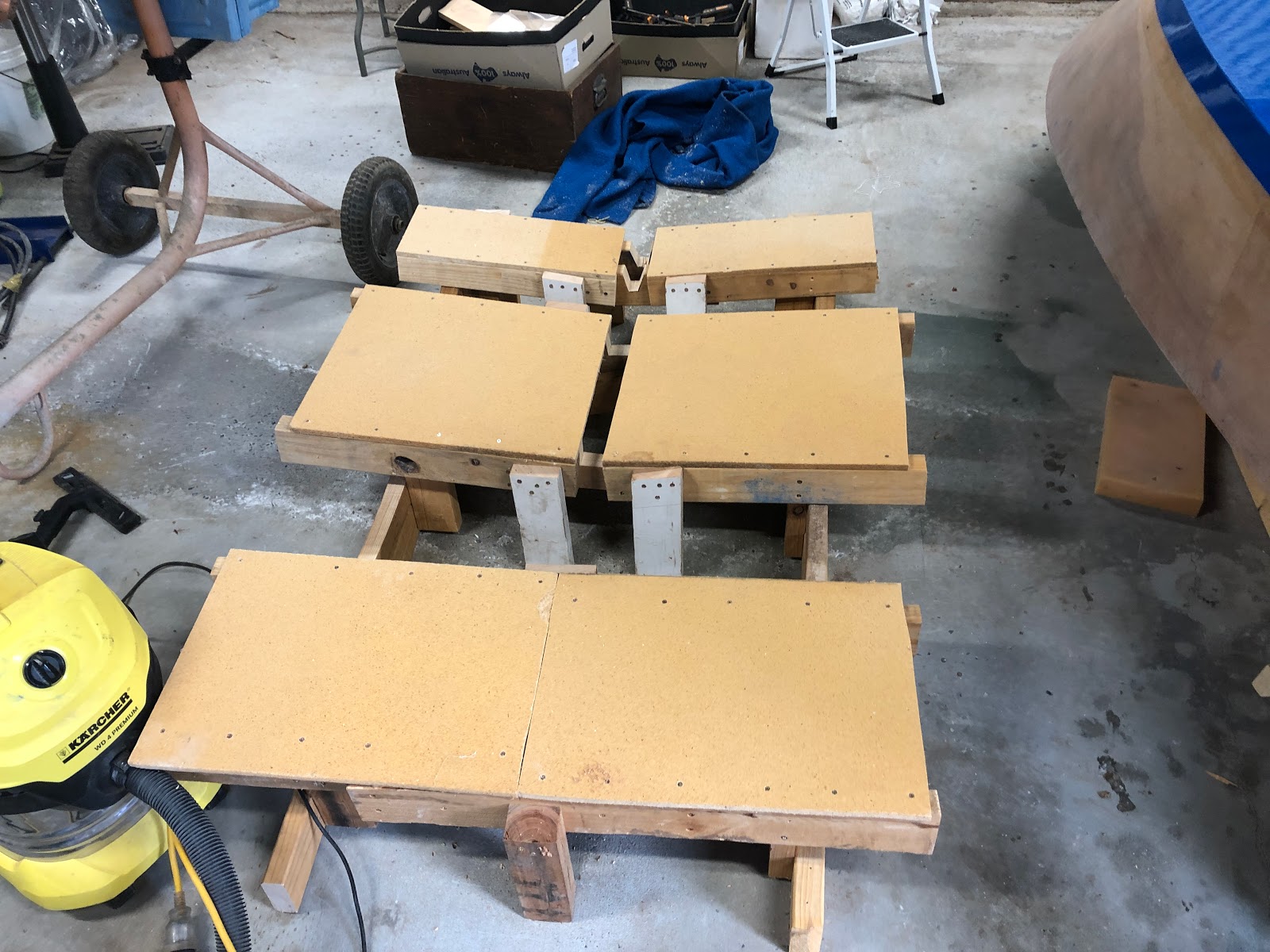
The first step was to create a bed for the boat to sit nicely on once it was flipped. The idea was to use some old foam mattresses to protect the paintwork and distribute the weight of the boat across a larger surface area of the hull.
Creating boat bed
The boat bed. Note the gap for the keel strip to go in.
I got up early on Monday (public holiday) and unscrewed the boat from the building form ready for the flipping. The plan was to move the boat onto a matress first, put the bed into position and then move the boat into its position on the bed.
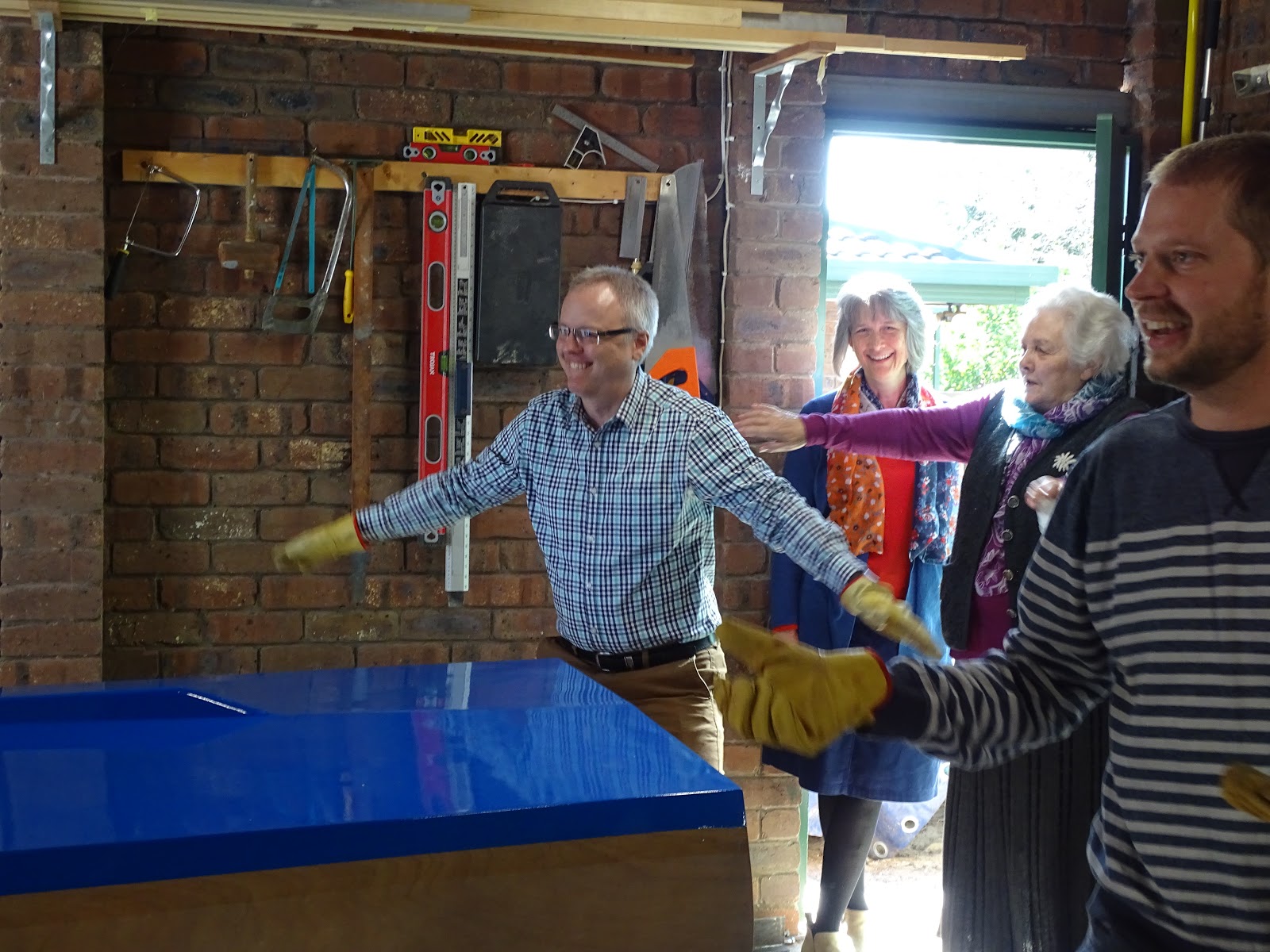
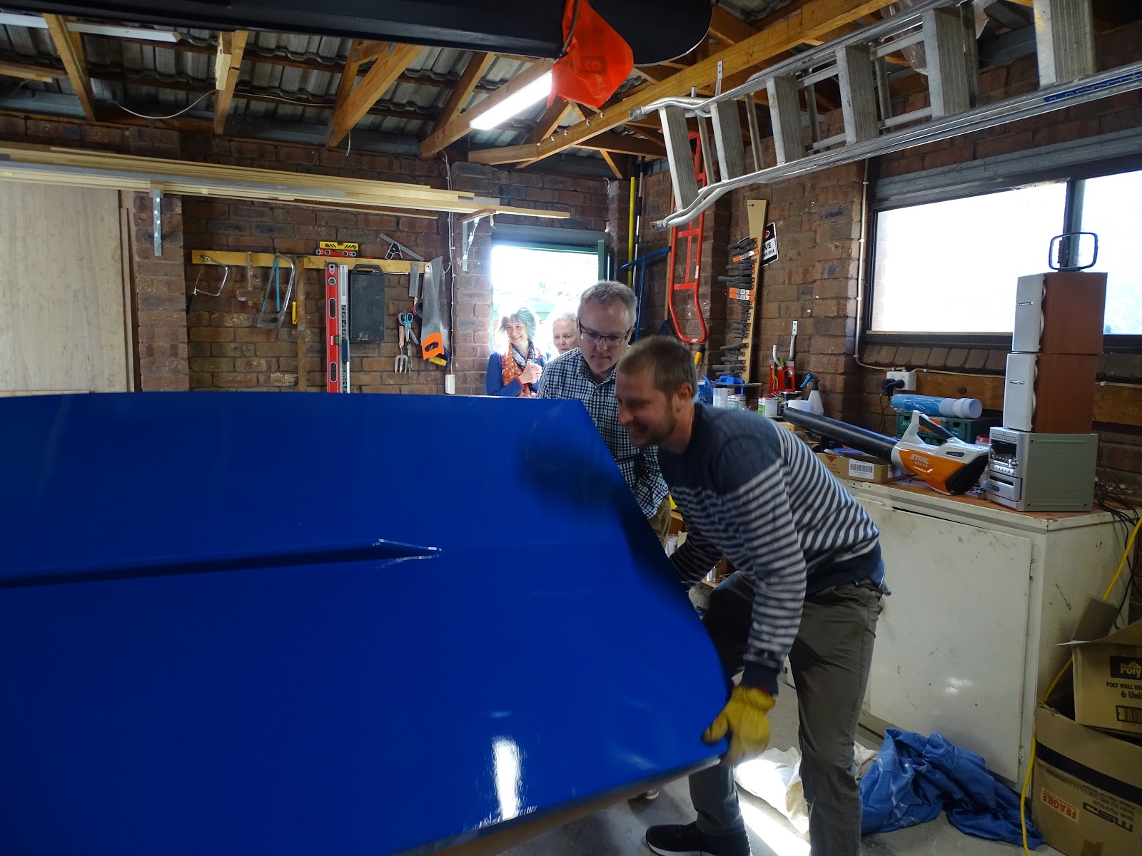
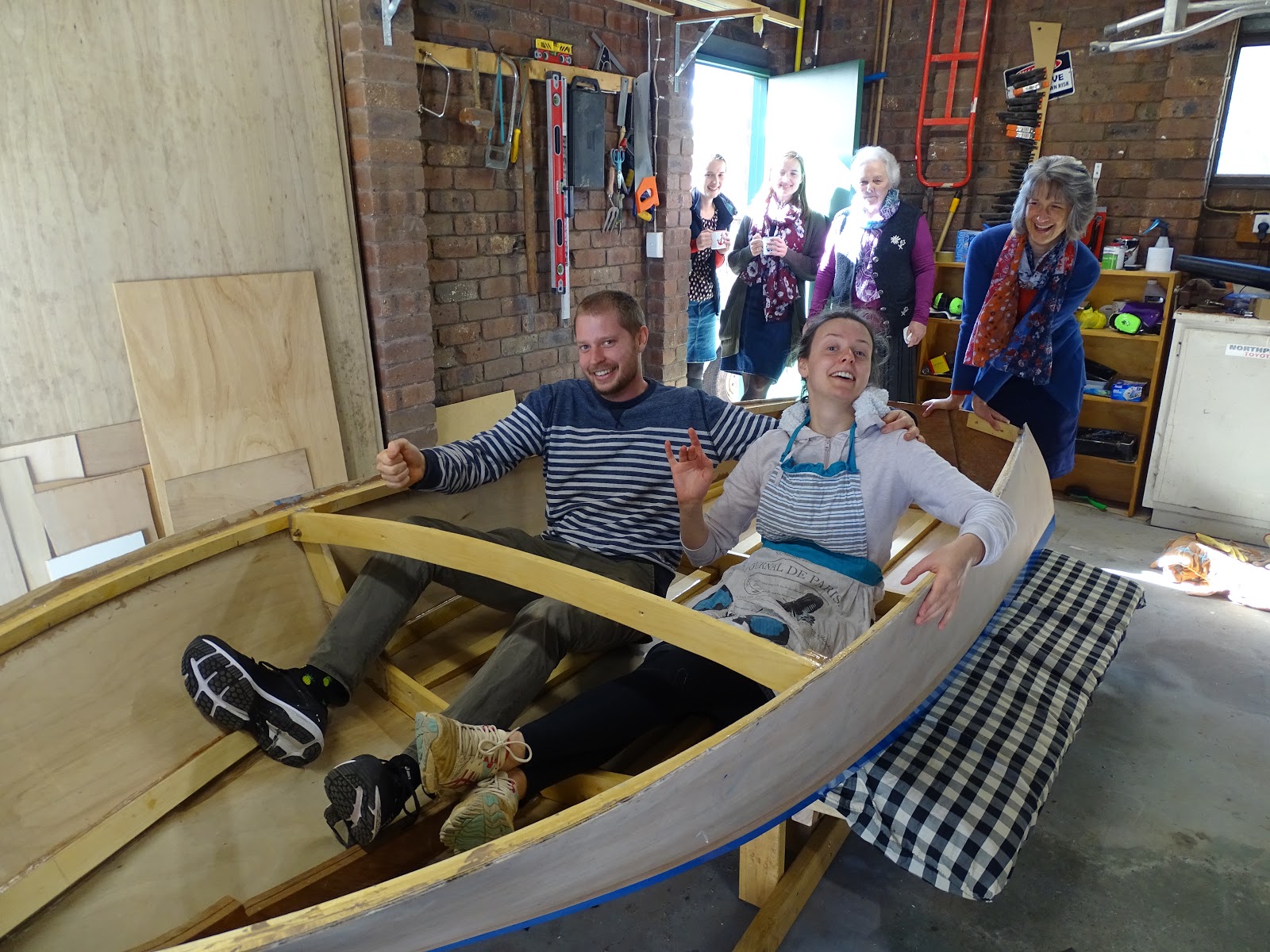
We invited Jo's family around for Brunch so they could help me flip the boat. There was lots of excitement and I like to think it was because of the boat more than the food!
We wore gloves to protect our hands from the sharp fiberglass edges.
Great excitement for the imminent flipping
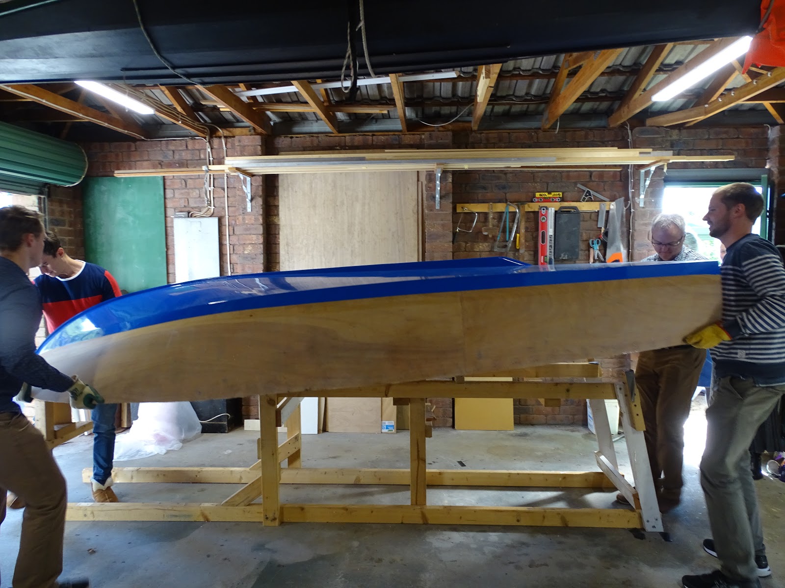
With an almighty "heave ho" we lifted the boat off the form. It was actually really light - two people could lift it.
Off the building form - its home for the last 6 years
Over it goes
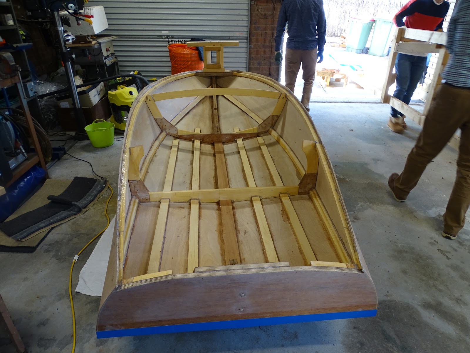
We placed the boat on a mattress so we could remove the building form and place the bed in position.
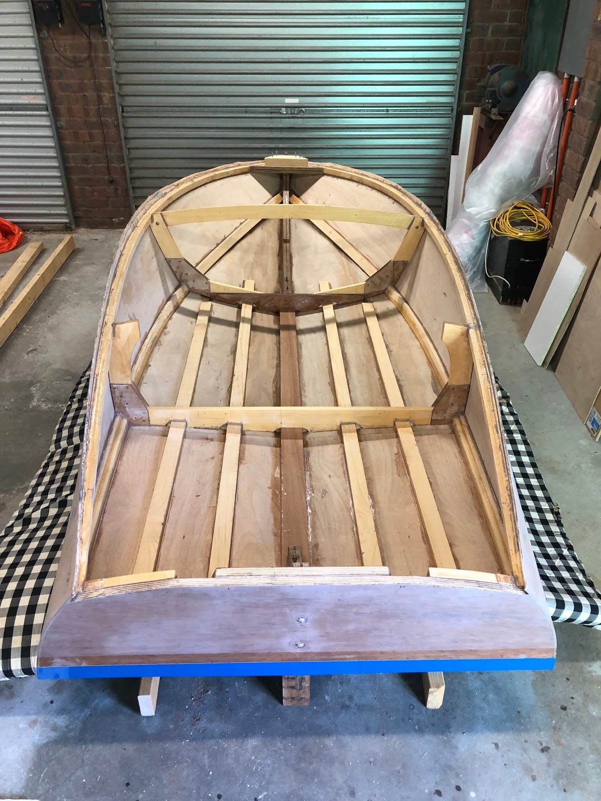
First glimpses of the inside of the hull
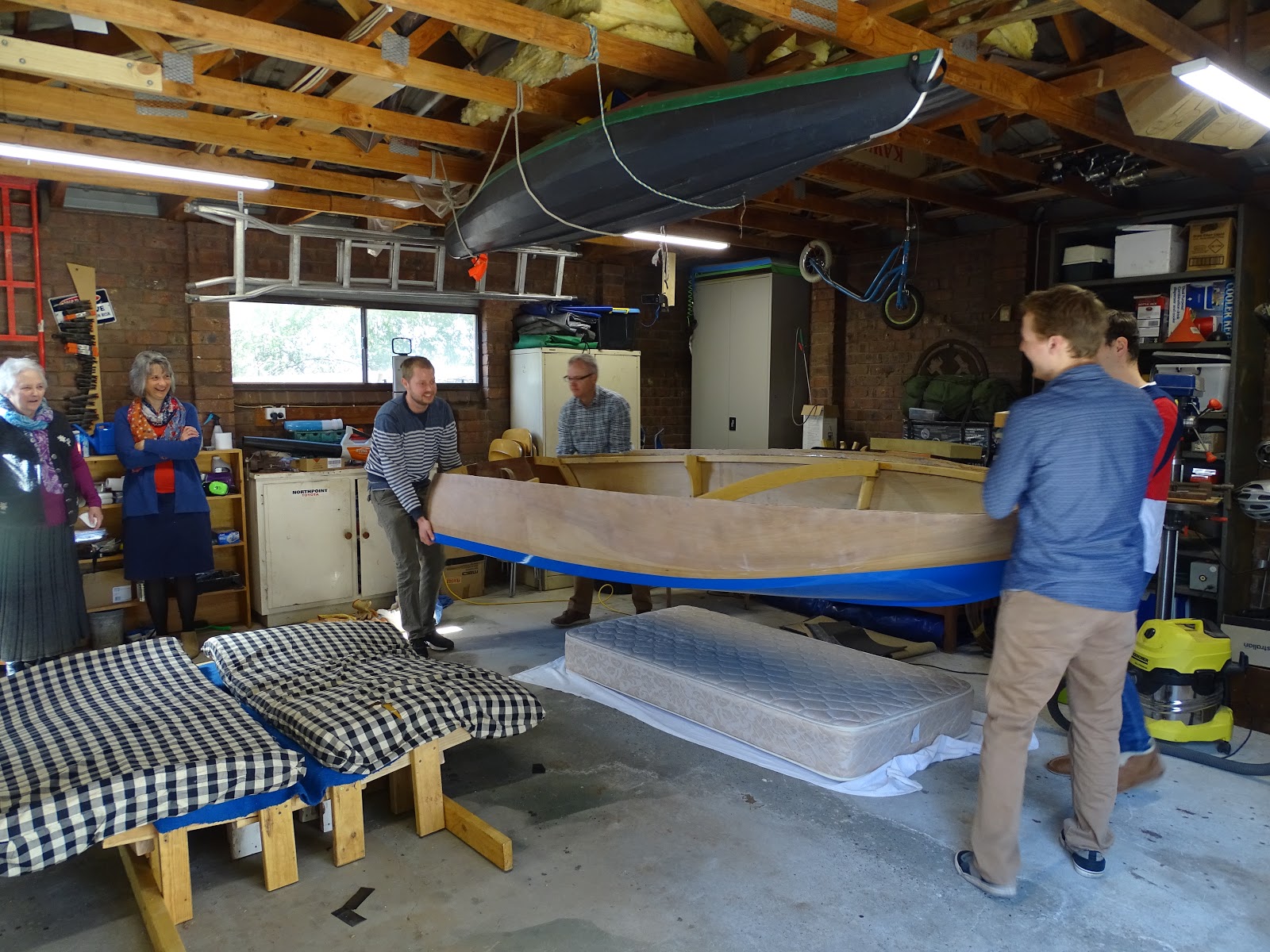
With the foam mattresses on the bed we lifted the boat into its final position.
Onto its bed
It was now time to try out the boat for the first time!
I told everyone that the excitement of the flip would be nothing compared to the excitement of the launch and that they better hope they are invited to the launch!
They will be - just don't tell them that yet ;-)
The first ride - lets hope the seat is more comfortable!
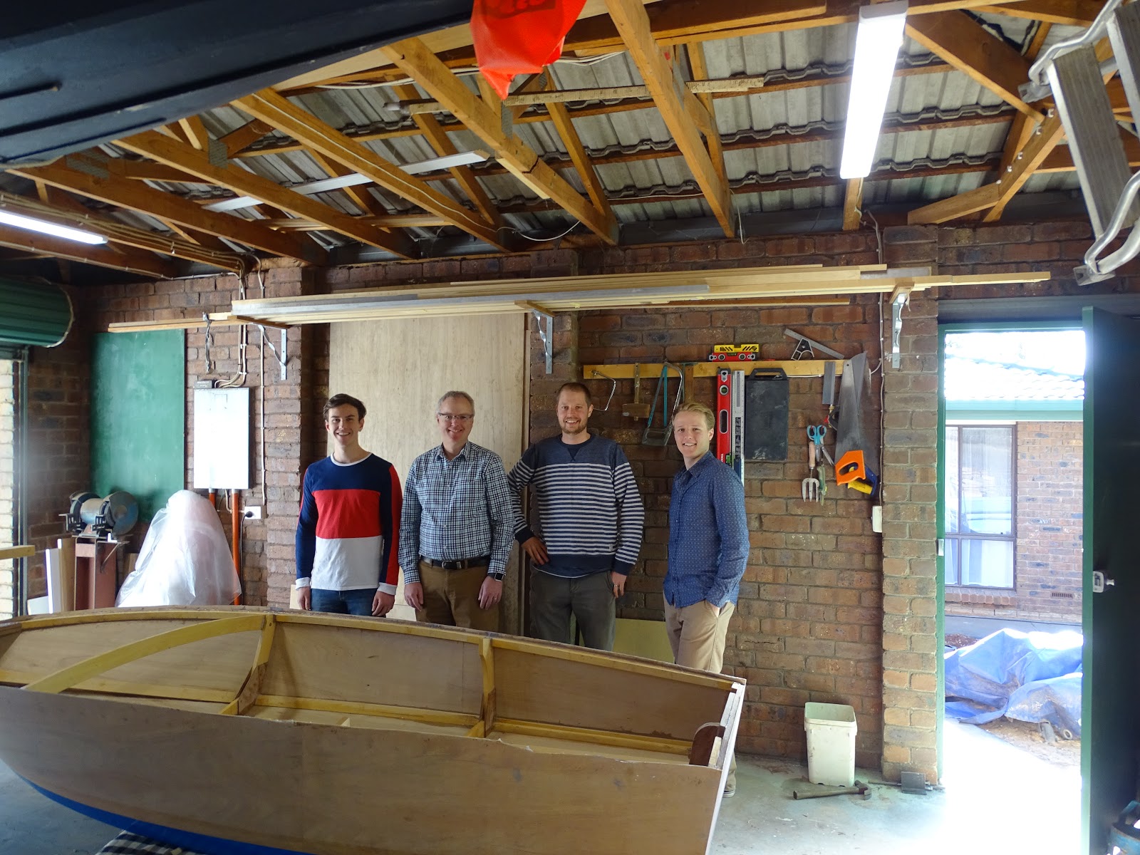
The boat wranglers. Father in law and Brothers in law.
Its just begging me to give it a internal fitout.
I wasted no time and that afternoon I installed the coamings.
It was out with the plans again to check the recommended method of installing them.
Consulting the plans
The coamings were made from two laminations of 7.5mm thick hoop pine. They bent very easily into position. Some angeled blocking was created to hold the coamings to frame 2. I just eyeballed it to make the coamings approximately vertical.
Coaming Blocking
Getting the correct angle at the transom was quite tricky. I had to creep up on the angle removing small amounts of material at at time. A sandpaper disk on the angle grinder worked well for this - it removes material very quickly.
Angle between coaming and transom - shown after gluing
As the the coamings are wedged between the transom and frame 2, they held in place without any clamps for the dry fitting.
Coaming dry fit
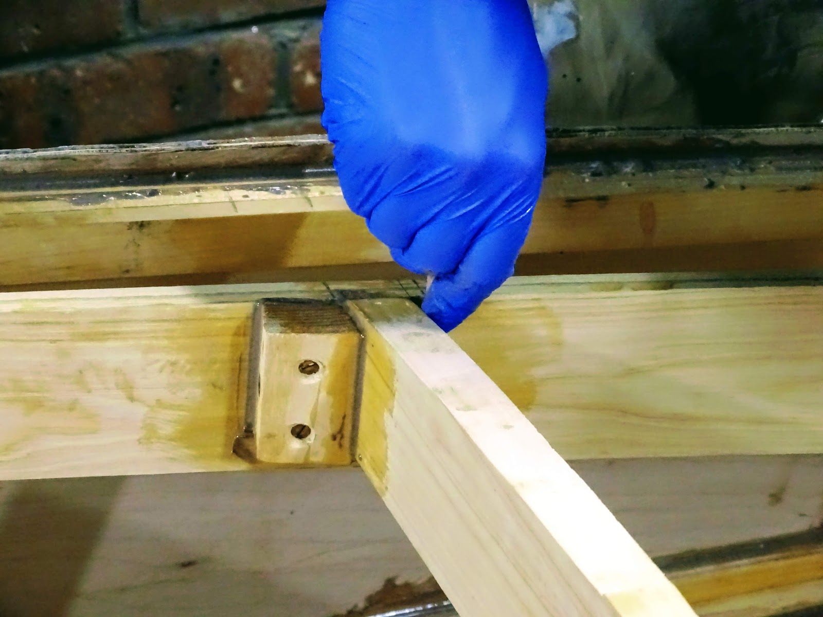
Epoxy was placed on all surfaces and given at least 15 minutes to seep into the wood before applying the thickened epoxy. This was to avoid dry joints especially where there is end grain. No screws were used on the coamings as the epoxy should be well strong enough and additionally it will also be further supported by the stern deck beams.
Coaming glue-up
Blocking glued and screwed in place
It feels like I am making really fast progress now. Part of me feels like I could finish the boat before the end of the year but the more experienced part of me says that this is unlikely. There's still lots of sanding to do before the boat hits the water!
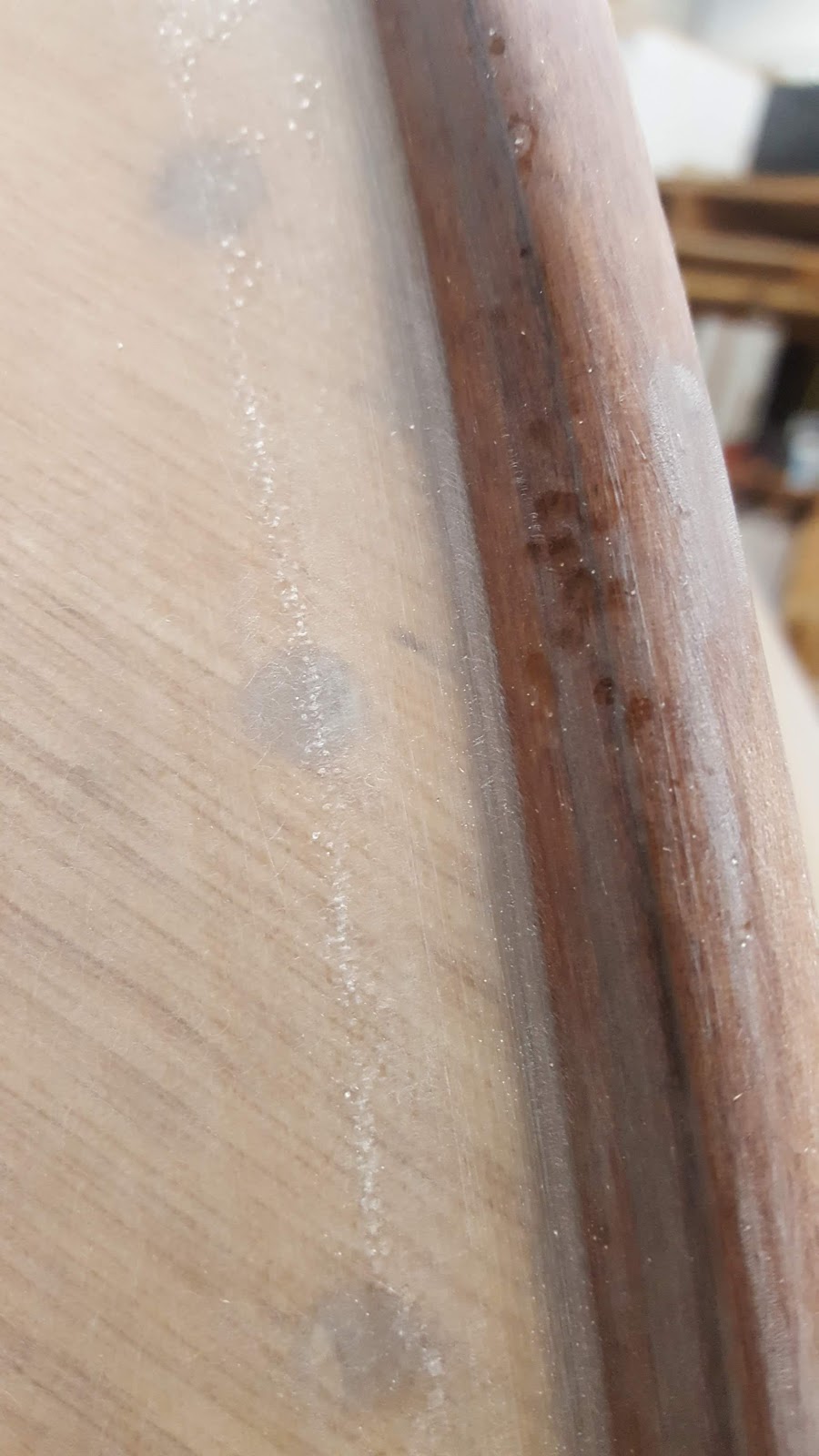
After a lot of time epoxying and sanding and sanding and sanding I was finally ready to paint the boat! Exciting!
Sanded keel strip
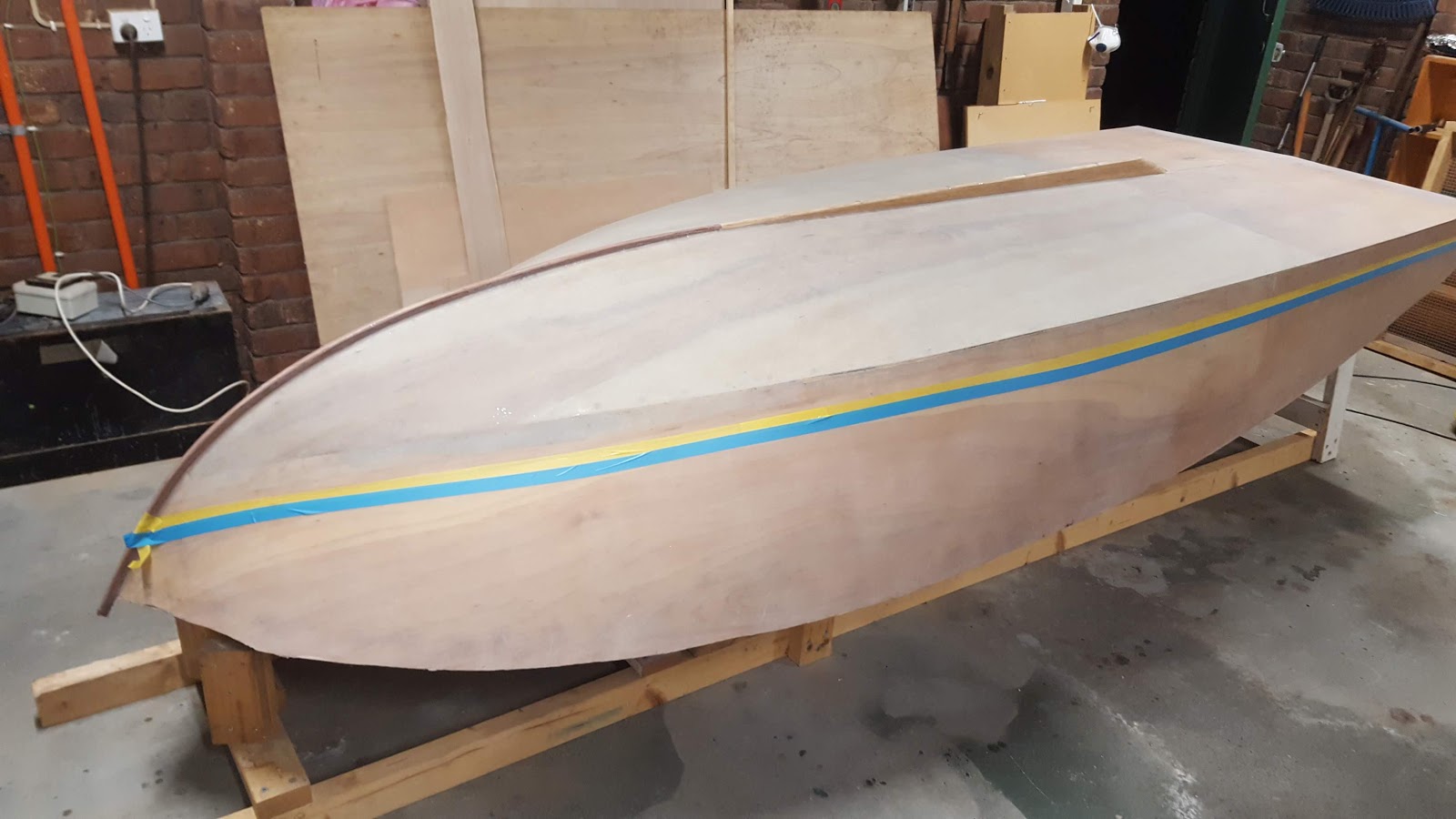
I purchased the best masking tape I could find at Bunnings because the plan was to leave the tape on for the whole paint job. The yellow tape shown in the image below was advertised to be able to stay on for 60 days without leaving a residue or sticking too strongly. I put a layer of cheaper blue tape below the yellow as I can easily sand off any sticky residue it leaves behind.
Masking the hull
It ended up being 223 days before I pulled off the tape! I got distracted by removing my swimming pool and landscaping my yard. Strength and stamina are to demolition what finesse and intelligence are to boat building.
I won't be using the demo saw on the boat!
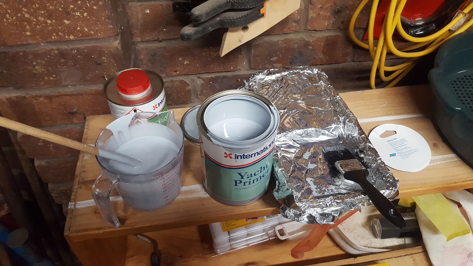
I got the tip of using aluminium foil in paint trays from one of the how to paint booklets produced by International Yacht Paint. It is a great tip which make the clean up a lot easier!
Getting primer ready
It was very satisfying putting the first strokes of paint on the boat. I was very happy how smooth it looked.
Starting to paint
Three coats of primer were put on the boat
Completed coats of primer
The next stage was to roll on some coats of the Pre-Kote undercoat. I tried tipping off the undercoat to avoid the 'orange peel' effect the foam roller left. I could not get the tipping off to work. The lines the brush left were worse than the orange peel that the roller left. I even experimented with different amounts of thinners but I could not get it to work. After two coats of undercoat it was time for some sanding to smooth out the bumps. On the third coat of undercoat I didn't worry about tipping off.
Undercoat
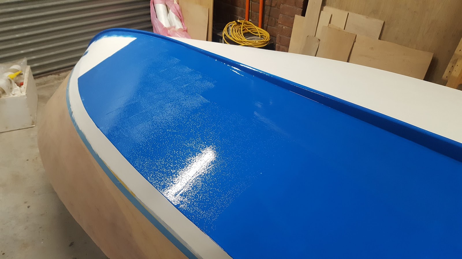
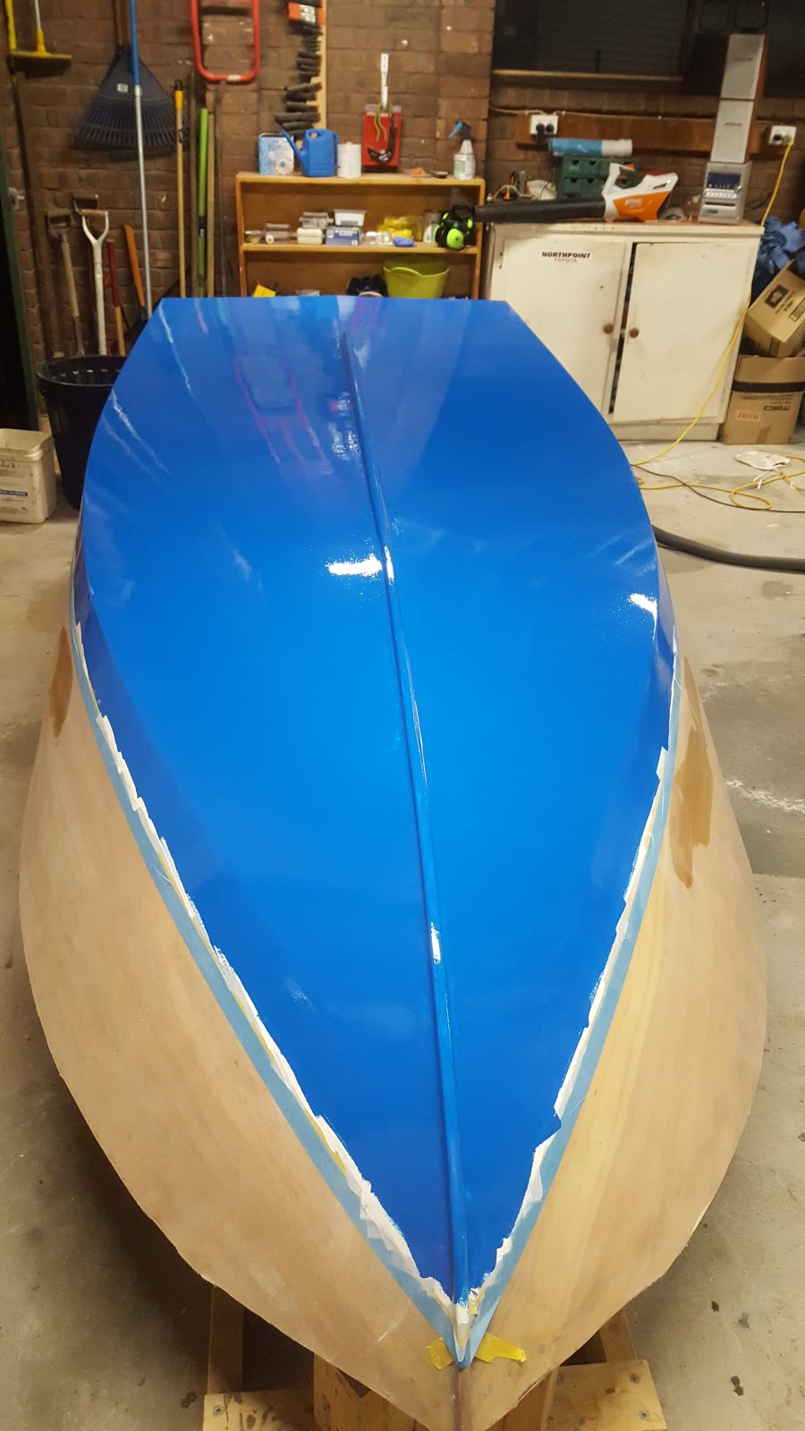
After carefully sanding with 280 and 320 grit sandpaper it was ready for the exciting step of putting on the color. When I opened the tin of Lauderdale Blue I was straight away in love with the color. It is a really nice looking blue!
International Yacht Paint Toplac - Lauderdale Blue
Its really rewarding seeing a beautiful color go on the boat!
The first few strokes feel so special - then you get used to it ;-)
Because of my lack of success with tipping off the undercoat, I initially decided not to bother tipping off the top coat. 'The orange peel doesn't look that bad after all - and it looks better than streaky lines", I thought to myself. But it transpired that the Toplac top coat is quite a different paint to the Pre-Kote undercoat. Rolling on the primer and undercoat left an orange peel effect. In contrast, rolling on the top coat left hundreds of tiny bubbles. I couldn't have the bubbles so I had to pick up a brush and start smoothing them out.... and that was when the magic happened!
The top coat tips off beautifully. You just run your brush gently over the paint and all the bubbles smooth out into a nice, even, flat, shiny surface! It was just so easy!
You dont need a super expensive brush for tipping off - just a reasonable quality brush with smooth thin bristles worked fine for me. I found that a brush about 30mm wide worked better than larger ones.
In the photo below the bubbles can be seen before the paint was tipped off.
Bubbles before tipping off
Half done
I was so happy with the finished first coat! I felt that it could not have gone better.
First coat completed
Originally the plan was to do two coats of top coat with a 320 grit sand in between coats to get a smoother finish. When sanding, I found that in many places it was cutting back to the white undercoat. It was at that point that I decided to do three coats of top coat. I gave it about a week of cure time before sanding.
Half sanded boat
Fully sanded boat
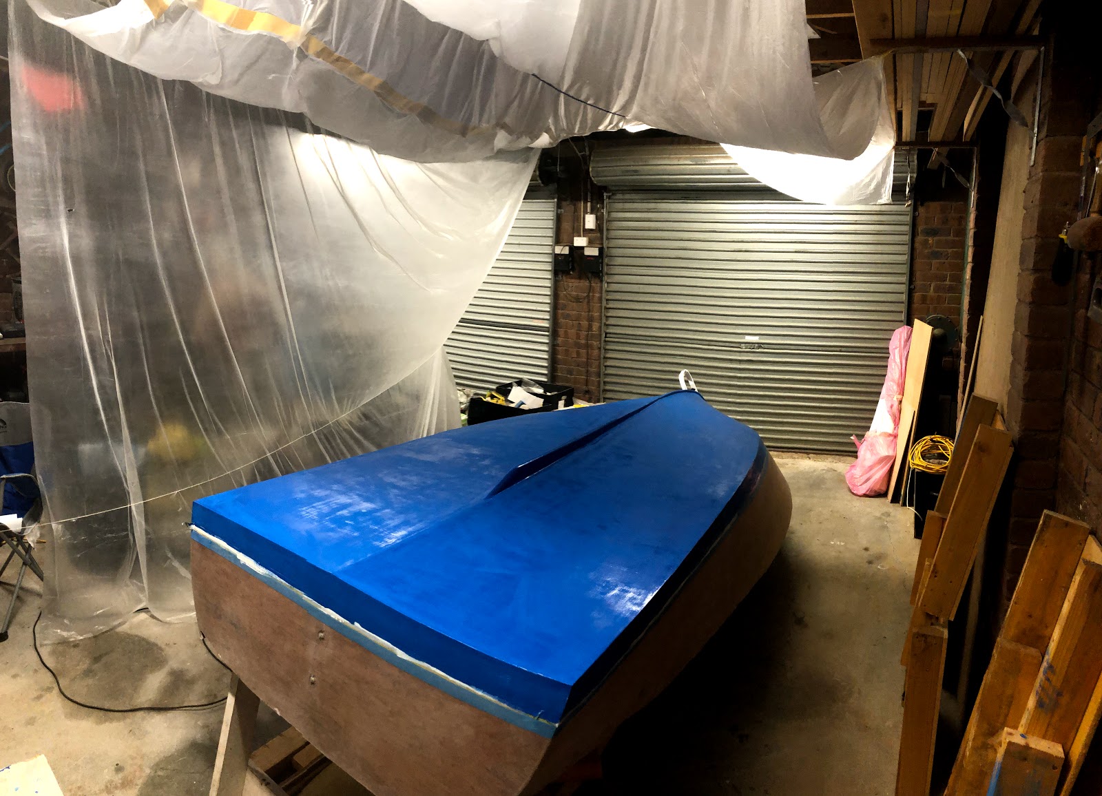
For the final coat I bought some cheap plastic drop sheets and hung them over the boat to give some protection from the dust. The floor was vacuumed the night before and the morning before to capture as much dust as I could.
Painting booth
The final coat went on nicely. I thinned the mixture slightly to get a better flow.
After half of the boat was painted, I noticed the paint in the tray had became thicker as some of the thinners had obviously evaporated. I noticed it was thicker because the tipping off was getting slightly more streaky. It was easy to fix by adding about 5mL of thinners to the paint tray and mixing it in.
I learnt that you can only paint a small bit at a time. This is because the time you have for effective tipping off is very limited. I found that you only have about 30 seconds max to tip off the paint before it starts to get more streaky. The trick I found is to not take too long before tipping off the join between an already tipped off section and a freshly rolled section. If you take too long the paint doesn't flow together and you seem to get a thicker streak line at the join. I rolled on the paint in sections from the keel to the chine about 300-400mm thick at a time.
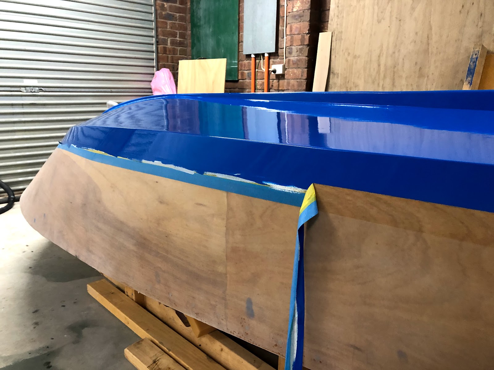
I was worried that after 223 days, the tape would be difficult to come off. I was particularly worried that after 9 coats the paint would be too thick and hard to tear off with the masking tape. There was no need to worry as it came off quite easily.
Removing the masking tape - final coat still wet
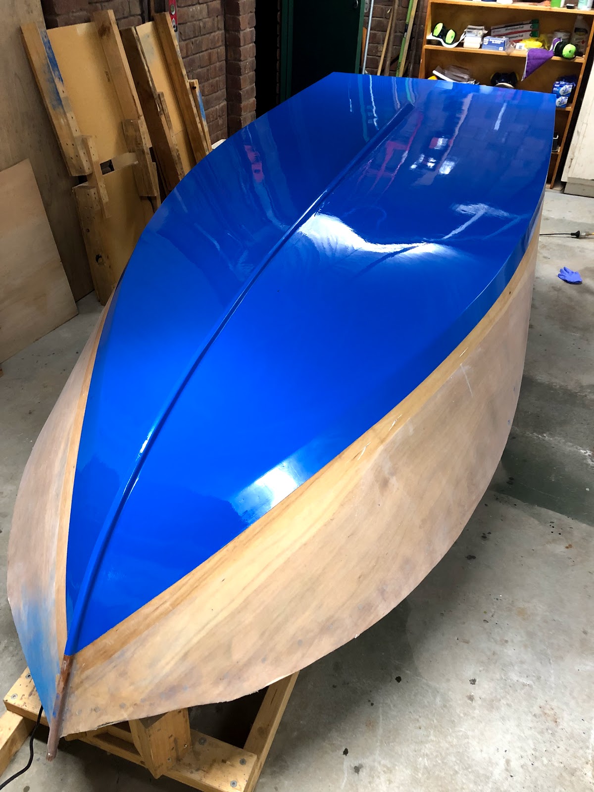
The blue looks darker in these photos compared to the earlier photos because I was using an iphone to take the photos instead of my Samsung.
The finished paint job. The blue in the bottom left is just dust that will sand off.
I am very happy with the result of the painting! It is not perfect - but it is definitely more than good enough!
I would recommend the single pack International Yacht paints I used. They were very easy to use. They do smell quite strong. I wore a mask while painting.
The next step is a EPIC MILESTONE!
Get ready for the BOAT FLIP!


